
Roof membrane, wall cladding, coping, and flashing all converge in a tight cross-section that has to manage water, air, and thermal movement simultaneously. Get one layer wrong, and water finds its way into the wall cavity, the masonry, or the structure below.
Poor detailing at this junction causes water infiltration, masonry deterioration, and expensive repairs, on both new construction and century-old landmarks. This guide breaks down parapet wall section anatomy, the major parapet types, where these details typically fail, and how to protect the joints that take the most abuse.
Key Takeaways
- Coping, cap flashing, membrane, and wall layers must stay continuous for water, air, and thermal control
- Most failures start at coping joints, sealant breakdown, or missing flashing beneath the cap
- Flush-edge, platform-framed, and balloon-framed parapets each demand different detailing approaches
- Flexible joint protection at masonry copings extends sealant life
What Is a Parapet Wall and Why Does Its Section Detail Matter?
The 2024 International Building Code defines a parapet as "the part of any wall entirely above the roofline." That's the legal definition. On the job, the parapet is only as good as the detail that finishes it.
Parapets trace back to fortification walls, where soldiers used raised barriers as cover. Today, they serve different purposes:
- Wind uplift protection at the roof edge
- Concealment for rooftop mechanical equipment
- Fall protection as a code-required safety barrier
What specifiers often miss is where failure actually starts. The wall assembly rarely fails on its own. Problems concentrate at the section detail: the cross-section where roof membrane, wall assembly, and coping cap meet.
At that junction, the four control layers (water, air, vapor, and thermal) must stay continuous. Design the wall correctly and still botch the section, and you get leaks anyway. Getting the transition right is what keeps the assembly dry.
Anatomy of a Parapet Wall Section: Core Components
A proper parapet wall section drawing should show the assembly from structure outward:
- Wall framing or masonry backup
- Sheathing and insulation
- Air/vapor barrier
- Roof membrane termination
- Cant strip at the inside corner
- Through-wall flashing
- Coping or cap flashing on top
The Four Control Layers
Per Building Science Corporation, parapets need continuous water, air, vapor, and thermal control layers across the roof-to-wall junction. Break any one of these, and you get a specific failure mode:
- Water layer breaks → active leaks
- Air layer breaks → drafts and pressure imbalances
- Vapor layer breaks → condensation within the assembly
- Thermal layer breaks → cold spots, condensation, energy loss

Coping Caps and the Highest-Stress Joint
The coping cap sheds water off the parapet top and keeps the façade below from staining. Good coping details slope inward slightly and include drip edges on both the front and back edge.
The masonry joints beneath and around that coping take the most punishment in the entire assembly. Thermal cycling makes the coping expand and contract daily, and every cycle works the sealant joint underneath.
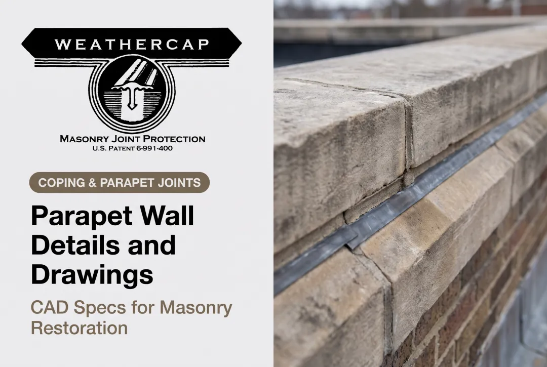
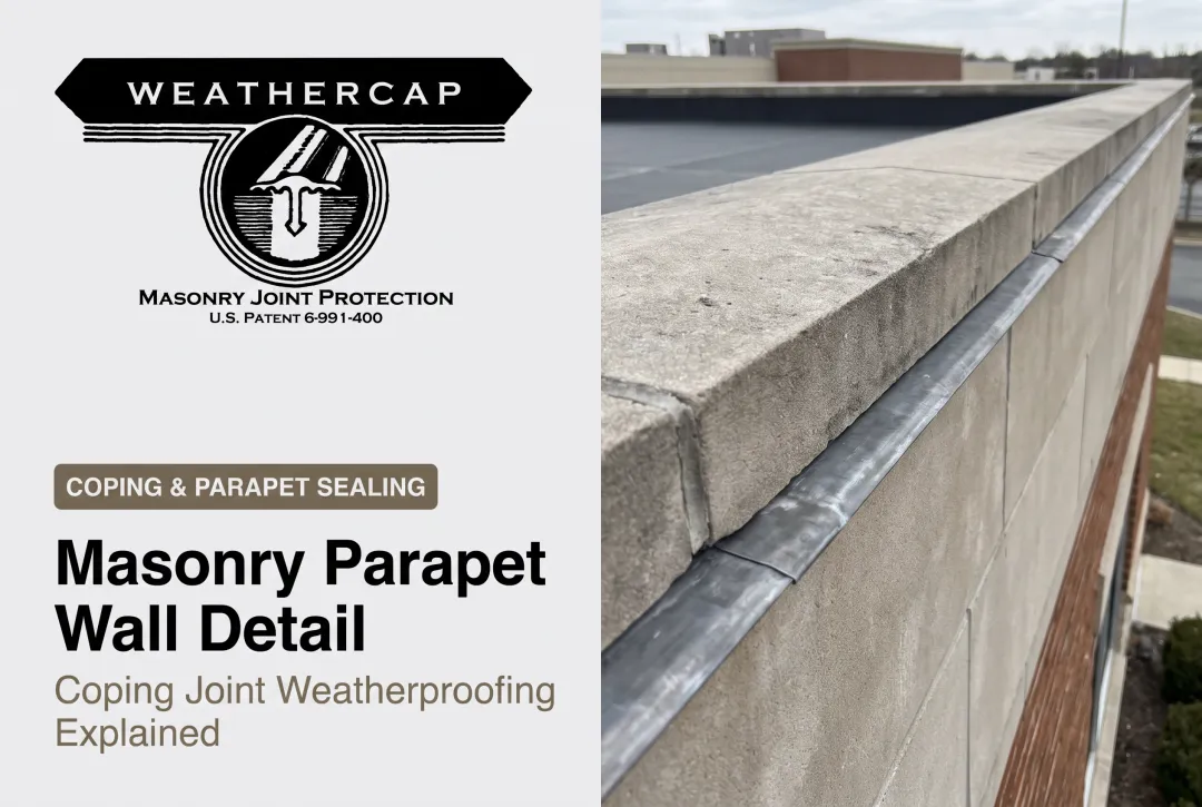
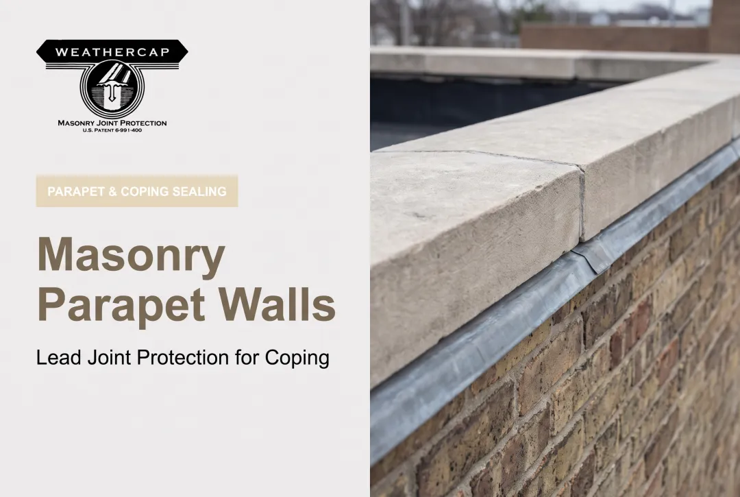
This is where a protective strip like WEATHERCAP® is interposed within the sealed masonry joint. The lead strip is bedded into the sealant and occupies part of the joint opening.
That cuts the effective joint opening by roughly half, so the sealant absorbs less movement. Less movement means less fatigue and longer sealant life.
WEATHERCAP comes in two configurations for coping applications:
- Type A (Flat Cap): top, side, and cross joints on copings, balustrades, and cornices (sizes A-2 through A-8; under 3/8" to 1.5" I.D.)
- Type B (90° Cove Cap): right-angle joints where cornices or projections meet a parapet or side wall (sizes B-2 through B-8)
Before you specify this condition, review a labeled cross-section that shows the cant strip, membrane lap, and coping together—the failure points become obvious in one view.
Types of Parapet Wall Sections and Their Detailing Differences
Not every parapet section is built the same way. The framing strategy changes what you need to detail.
Flush-Edge Parapets
The roof structure sits directly above the wall, with no offset. This is the simplest configuration to build, but it offers the least wind-uplift protection of the common types. Detailing is straightforward, but performance margins are thin—roof-edge fastening and flashing do most of the work.
Platform-Framed Parapets
Here, the roof structure acts as a platform, and the parapet wall gets built on top of it. This requires:
- Lateral bracing to resist wind loads on the exposed parapet
- Careful load-path detailing where the parapet transfers weight down to the platform
- Continuous flashing and WRB detailing at the platform-to-parapet junction
Balloon-Framed Parapets
The wall assembly bypasses the roof system entirely and continues straight up past the roofline. Because the wall isn't interrupted, air barrier continuity becomes the central challenge. Closed-cell spray foam is a common strategy here, since it maintains an unbroken air seal where the wall crosses the roof plane.
Masonry Parapets
Concrete or masonry decks often function as their own air control layer. The catch: every joint still needs careful sealing—especially coping and control joints—or you lose the air- and water-control benefit the mass assembly otherwise provides. Building movement opens those joints over time, so the seal has to flex and stay protected, not just look tight on day one.

Common Failure Points in Parapet Wall Sections
Parapet failures follow patterns. Once you've seen a few, they're predictable.
Sealant and caulk joint failure ranks as the leading cause of parapet leaks. Buildings shift from thermal, structural, and seasonal forces. Unaccommodated movement stresses the sealant until it cracks or debonds.
Missing or discontinuous membrane beneath the coping is the second major pathway. If the roof membrane or through-wall flashing doesn't extend continuously under the cap, water gets a direct route into the wall.
Thermal bridging occurs when roof insulation doesn't connect to wall insulation at the parapet. This creates a cold spot where condensation forms inside the assembly, often invisible until damage is already underway.
IIBEC's case study on "The Last Few Feet: Parapet Design, Issues, and Repair" documents real masonry parapet failures: water migrating past flashing systems, cracking and distress in parapet masonry, and even inward displacement of the parapet wall itself.
In one case, the recommended fix required disassembling the parapet entirely—a costly outcome better detailing upfront would have prevented.
A quick summary of failure origins:
| Failure Point | Root Cause | Consequence |
|---|---|---|
| Sealant/caulk joints | Unaccommodated movement | Cracking, leaks |
| Missing membrane under coping | Discontinuous water layer | Direct infiltration |
| Thermal bridging | Insulation gap at junction | Condensation, damage |
Best Practices for Designing and Protecting Parapet Wall Sections
A few disciplined habits separate parapets that last decades from ones that need repair every few years.
Simplify material transitions. Every additional cladding material meeting at the parapet-to-wall interface adds a seam, and every seam is a potential leak path. Fewer transitions mean fewer vulnerabilities.
Wrap continuous insulation over the parapet, rather than relying on cavity insulation alone. This keeps the thermal layer unbroken across the roof-wall junction and directly addresses the thermal bridging problem covered above.
Specify joint protection at coping and right-angle junctions. This is where WEATHERCAP has a documented track record. The system is specified in the GSA Historic Preservation Technical Procedures (Document 07656-01) for landmark restoration work, with an installation process that includes:
- Measuring the joint and adding ¼ inch for anticipated movement
- Cleaning and preparing the joint surface
- Filling with sealant to roughly ⅛ inch above the masonry surface
- Pressing the pre-contoured cap into the sealant bed, keeping the anchor shaft fully surrounded
- Joining sections with mitered, coped, or butted seams using full 6-foot lengths

Weathercap's portfolio includes restoration work on the Washington Monument, the U.S. Supreme Court, and the Smithsonian Institution. Those projects leave no margin for joint failure.
Build a mock-up before full installation, especially on complex or historic parapet conditions. ASTM E2099 covers the specification and evaluation of pre-construction mock-ups for exterior wall systems.
Treating a failed mock-up test as useful information, not a setback, saves far more money than skipping the step.
Frequently Asked Questions
What exactly is a parapet wall?
A parapet wall is a vertical extension of a building's wall that rises above the roofline. It serves safety, fire-separation, and wind-uplift protection functions required under most building codes.
What is another name for a parapet wall?
Historically, parapets were known as breastworks, from the Italian parapetto (a breast-high wall). In modern construction, "parapet" is the standard term. Coping and cap refer only to the top covering, not the wall itself.
What is the difference between a concrete fascia and a parapet?
A fascia is a non-structural trim band or panel at the roof edge. A parapet is a structural wall extension rising above the roofline. The two aren't interchangeable terms.
What causes most parapet wall leaks?
Sealant and caulk joint failure from unaccommodated thermal movement is the top cause, closely followed by missing flashing continuity beneath the coping.
How can I extend the life of sealant joints on a parapet coping?
Flexible joint protection systems buffer movement stress before it reaches the sealant. Weathercap's soft lead strip approach reduces the effective joint opening by roughly half, easing the load on the sealant itself.
Do parapet walls need waterproofing membranes?
Yes. A continuous membrane beneath the coping is essential. Without it, water has a direct path into the wall assembly below.