
Many architects and drafters struggle to translate physical coping assemblies into accurate CAD or BIM details. Slope, joints, and movement allowances are easy to overlook and expensive to fix once installed.
This guide walks through standard components, step-by-step CAD/BIM drafting approaches, and specification best practices for metal coping details that actually hold up.
Key Takeaways
- Show slope, drip edges, cleats, and joint spacing on every coping CAD detail so the assembly functions correctly
- Draft coping details in AutoCAD (2D polylines/blocks) or Revit (profile families/sweeps), the two dominant workflows
- Specify joint protection systems like WEATHERCAP® in coping details to prevent sealant failure
- Follow GSA Historic Preservation Technical Procedures for federal and institutional coping specifications
What Is Metal Coping and Why Its CAD Detail Matters
Metal coping is the formed metal cap installed atop parapet walls, chimneys, and freestanding masonry to shed water away from the wall assembly below. It's usually the single most exposed component on a building envelope, taking direct sun, wind, and thermal cycling year-round.
CAD details communicate critical fabrication and installation data to contractors and fabricators, including:
- Metal gauge and material type
- Slope direction and pitch
- Overlap and seam locations
- Fastening method (exposed vs. concealed)
The consequence of sloppy detailing is real. The Whole Building Design Guide directs designers to detail parapets so they're properly flashed to prevent roof leaks. That guidance reflects how often poor coping detailing shows up in envelope failure investigations.
A coping detail is the instruction set a sheet metal shop follows to bend, hem, and lock a product that will sit exposed to weather for decades.

Why Drafters Get This Wrong
Most detailing mistakes trace back to one root cause: treating coping as a static object instead of a moving system. Metal expands and contracts with temperature swings, and a detail that doesn't account for that movement is a detail that will eventually fail.
Essential Components of a Metal Coping CAD Detail
A complete coping detail needs several elements working together. Missing any one of them creates a weak point.
Profile Shape and Dimensioning
Coping profiles typically come in three shapes: flat, sloped, or cove. Regardless of shape, the Copper Development Association's Architecture Handbook recommends sloping the cover toward the roof side, not outward, to reduce water dripping over the exterior face.
Your section view should dimension:
- Overall height and depth of the coping cap
- Overhang past the wall face on both sides
- Slope angle or rise-over-run
Drip Edges and Hems
The drip edge directs water away from the wall face instead of letting it run down the masonry. CDA's illustrated details use a ¾-inch drip as a working example — not a universal code minimum, but a useful reference point when no manufacturer spec is available.
Cleats and Continuous Cleat Systems
Continuous cleats anchor coping to the substrate without exposed fasteners, which keeps water from finding a path through screw penetrations. In section view, cleats appear as a hooked or hemmed strip locked into the coping's underside edge, fastened to blocking below.
Expansion Joint Spacing
CDA specifies a maximum 30-35 foot run for loose-locked copper coping pans before an expansion-seam detail is required. That figure applies to copper only—not aluminum or other metals.
Annotate joint spacing clearly on plan-view call-outs. Never assume one metal's movement tolerance applies to another.
Joint Protection at Coping-to-Parapet Transitions
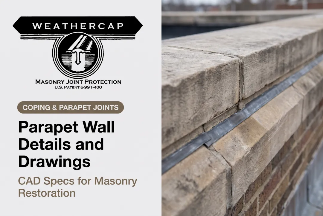
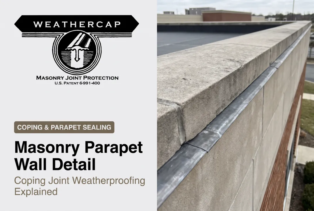
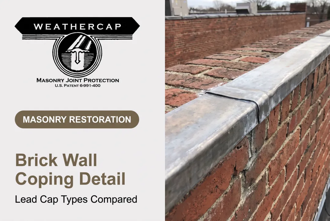
Profile, cleats, and expansion spacing still leave one weak point: the right-angle junction where coping meets the parapet face. That joint takes repeated movement stress, so CAD details should show a soft, flexible interposed strip—such as WEATHERCAP®'s patented lead strip—in the sealant assembly.
Install WEATHERCAP as part of the sealant system, not against masonry or backer rod. Press it into a sealant bed at the joint, then turn it down at least 1 inch over the coping face. Per internal specification data, the strip buffers movement stress and reduces joint opening by half when placed between sealant layers, which extends sealant life compared with caulk alone.
For coping work, WEATHERCAP Type A (flat cap) covers top, side, and cross joints in five sizes:
| Size | Joint I.D. (under) | Outside Coverage |
|---|---|---|
| A-2 | 3/8 in. | 9/16 in. |
| A-3 | 7/16 in. | 11/16 in. |
| A-4 | 3/4 in. | 1 in. |
| A-6 | 1 1/4 in. | 1 1/2 in. |
| A-8 | 1 1/2 in. | 2 in. |

Use Type B (90° cove cap) where cornices, belt courses, or projections meet a parapet at right angles.
Material and Finish Callouts
Detail notes should specify the metal (aluminum, copper, stainless steel, or lead-coated copper) plus gauge and finish. CDA's copper benchmark of 16-20 oz/ft² is well documented for copper flashings and copings. No equivalent general standard covers aluminum or stainless, so confirm those against the manufacturer's spec sheet.
How to Create Metal Coping Details in CAD and BIM Software
The AutoCAD Approach
Most 2D coping details begin as a full-scale polyline profile that defines slope, drip, hem, and cleat pocket:
- Draw the cross-section at full scale using polylines
- Convert the profile into a reusable block for consistent reuse across plan sets
- Consider a dynamic block if you need adjustable overhang or height parameters
- Add annotation layers for material callouts, dimensions, and joint spacing notes
The Revit/BIM Approach
Revit's official workflow uses a Profile Hosted family applied as a wall sweep. According to Autodesk's Revit help documentation, the process runs like this:
- Start with a Profile family template
- Draw a single closed-loop profile representing the coping cross-section
- Set Profile Usage to "Wall Sweep" in the family editor
- Load the family into your project and apply it via the Wall Sweep tool

Avoiding the Outward-Sloping Corner Error
A common Revit headache: sweeps that fail to join cleanly at corners, sometimes producing a profile that appears to slope outward instead of toward the roof.
The documented fix is to adjust the endpoint grip and set Wall Corner Join to Miter in the sweep properties. If two adjacent sweeps still won't clean up automatically, manually modify the return to miter with the adjacent sweep end.
Linking to Wall Type and Parapet Height
Link your coping profile family to wall type parameters so it scales correctly as parapet height varies across the building. A family that's hardcoded to one wall condition will misbehave the moment it's applied elsewhere in the model.
Cross-reference manufacturer CAD resources where available. Weathercap, for instance, distributes illustrated Type A and Type B application details as a PDF covering both horizontal and perpendicular joint conditions. Use those dimensions to confirm geometry before you finalize your own family.
Common Detailing Mistakes and Best Practices
Mistake 1: Applying a full parapet cap profile to partial-height walls. When a wall doesn't reach full parapet height, forcing a wall-type-embedded coping profile onto it creates geometry errors. Use a sweep instead — sweeps aren't tied to the wall's overall height and can be positioned independently.
Mistake 2: Omitting expansion joint spacing. This is the mistake most likely to cause field failures. Without a defined movement joint, thermal expansion has nowhere to go, and the Copper Development Association (CDA) notes that unrelieved stress can buckle copper coping outright.
Mistake 3: Ignoring documented movement history. A 2013 IIBEC case study on a nine-story building found that a parapet detail included vertical expansion joints but omitted horizontal ones. Calculated differential movement reached roughly 1.2 inches, and by the time it was documented, parapets had leaned inward as much as 4-6 inches.
The repair required steel-stud framing, new aluminum coping, vertical expansion joints, and coordinated flashing. That case is a useful reminder: expansion joints aren't optional line items—they're the difference between a system that lasts decades and one that needs a full parapet rebuild within 20 years.

Best practices to lock into the CAD set:
- Model partial-height walls with sweeps, not full parapet cap wall types
- Define expansion joint spacing before the coping profile is placed
- Detail both vertical and horizontal movement joints where differential drift is expected
- Cross-check the detail against the building's documented movement history
Specifying Metal Coping for Historic and Institutional Projects
Federal and institutional projects — national monuments, courthouses, university buildings — often require compliance with GSA Historic Preservation Technical Procedures. The relevant document, "Installing Lead Stone Flashing to Protect Masonry Joints," covers vulnerable masonry joints at parapets, copings, balustrades, cornices, and belt-course ledges.
Section 3.03 of that procedure requires:
- Full-length strip installation where possible
- End turn-down of at least 1 inch over the front and back faces of copings
- Joints neatly mitered, coped, or butted for a weather-tight fit
Specifying a patented joint protection product in the CAD detail gives architects a documented, GSA-referenced solution instead of a generic sealant callout.
WEATHERCAP has been used on projects including the Washington Monument, U.S. Supreme Court, and Smithsonian Institution. Its inclusion in GSA technical procedures gives specifiers a paper trail that satisfies review boards.
Manufacturers typically provide supporting documentation directly to the design team, including:
- Sample specification language (general, product, and execution sections)
- MSDS documentation for safety compliance
- Illustrated CAD reference material showing Type A and Type B applications
Adding this material directly into detail sheets saves coordination time compared to drafting joint protection details from scratch.
Frequently Asked Questions
What is the difference between metal coping and flashing?
Coping caps the top of a parapet or wall to shed water off the top surface. Flashing is a broader category that diverts water at joints, penetrations, or transitions lower in the assembly. The two work together but serve different locations.
What gauge of metal is typically used for coping?
Copper coping commonly runs 16-20 oz/ft², per Copper Development Association guidance. Aluminum and stainless steel gauges vary by manufacturer, wind exposure, and system design, so always confirm against the specific product's technical data.
How do you draw a coping detail in Revit?
Build a Profile family using a single closed-loop cross-section, set Profile Usage to Wall Sweep, then load and apply it to your wall through the Wall Sweep tool. Adjust corner joins to Miter if sweeps don't clean up automatically.
How far apart should expansion joints be in metal coping?
For copper, loose-locked pan runs typically max out around 30-35 feet before requiring an expansion seam. That figure is copper-specific. Other metals need their own movement calculations based on manufacturer specs and local climate.
Why do metal coping joints fail over time?
Building movement, thermal expansion and contraction, and sealant degradation are the primary culprits. Without a joint protection buffer or adequate expansion joint spacing, stress concentrates at the sealant and eventually breaks the seal.
Can CAD coping details include third-party joint protection products?
Yes. Manufacturers like WEATHERCAP® provide CAD reference material and sample specification language you can drop straight into a project's coping detail sheets.