
Unmanaged cracking isn't just cosmetic. It opens a path for water, which leads to spalling, corrosion of embedded steel, and expensive repairs. A properly detailed control joint solves this by giving movement a planned place to happen.
This guide covers what a control joint actually is, how it differs from expansion, isolation, and construction joints, proper spacing and depth guidance, and how to protect the joint's sealant once it's installed. It's written for contractors, architects, and preservation specialists working on masonry and concrete facades.
Key Takeaways
- Control joints are intentional weak planes — they direct cracking, they don't prevent it
- Expansion, isolation, and construction joints differ in purpose and reinforcing detail
- CMU spacing commonly maxes out around 25 ft, with a 1.5:1 length-to-height ratio limit
- Sealant inside a control joint degrades over time and benefits from added mechanical protection
What Is a Control Joint?
A control joint is a vertical (or occasionally horizontal) weak plane built or cut into masonry or concrete to control where shrinkage cracking occurs, rather than stopping cracking altogether.
CMHA describes it as a joint that divides a large concrete masonry field into separate panels so shrinkage happens with less random cracking. It acts as a plane of reduced restraint that permits longitudinal movement.
Here's the reality contractors run into constantly: CMU, precast, cast stone, and concrete slabs all shrink over time. That shrinkage is going to crack the material somewhere. The only question is whether you choose the location or let the material choose for you.
Two mechanisms work together to manage this:
- Control joints: physical weak planes (tooled, sawed, or raked) that concentrate stress at a known location
- Horizontal/bed joint reinforcing: steel that spreads shrinkage stress across a wider area, reducing the tendency to crack at all
Most control joints get sealed with a flexible sealant or caulk. As the wall or slab moves, the joint widens and narrows, and the sealant needs enough flexibility to keep tracking that movement without tearing or debonding.
Control Joints in Concrete Slabs
For slabs, the industry term is often "contraction joint" (same function, different name). According to ACI's own FAQ, conventional saw cuts should generally be one-quarter of the slab depth, based on ACI 327R-14. Early-entry saws can work at a shallower depth.
Timing matters just as much as depth. Cuts are typically made 4 to 12 hours after placement (or 2 to 6 hours with early-entry saws), late enough that the surface can resist blade damage and early enough to beat random shrinkage cracking.
A common question: does a small 10x10 ft slab need a joint? Using the general industry practice range of roughly 24 to 36 times the slab thickness, a 4-inch slab lands around 8 to 12 ft between joints.
A 10 ft panel often falls within that range on its own. Reinforcing, mix design, and restraint conditions can change the answer, so don't treat the range as a blanket rule.

Control Joint vs. Other Joint Types
The fastest way to sort out joint terminology: ask whether the joint exists because of material movement or because of construction sequencing.
- Movement-driven joints: control, expansion, isolation
- Schedule-driven joints: construction joints
Construction joints mark where one concrete placement stopped and the next began. They typically carry continuous reinforcing through them because they're not designed to accommodate ongoing movement. They're a pour-sequence detail, not a crack-control feature.
Control joints work the opposite way. Reinforcing that would restrain the intended movement (bed-joint steel, nonstructural bond-beam bars) gets discontinued at the joint. Structurally required steel, though, generally stays continuous.
Expansion and isolation joints sit in a different category. Rather than a shallow cut or raked mortar joint in continuous material, these use a compressible filler and no rigid material bridging the gap. ACI's terminology confirms isolation joints interrupt all bonded reinforcement, while expansion joints interrupt some or all.
| Joint Type | Purpose | Reinforcing | Sealant Approach |
|---|---|---|---|
| Control/contraction | Directs shrinkage cracking | Nonstructural steel discontinued | Sealant in shallow cut/raked joint |
| Expansion | Accommodates dimensional growth | Some/all interrupted | Compressible filler |
| Isolation | Separates elements entirely | All interrupted | Compressible filler, full separation |
| Construction | Marks pour-stop location | Continuous | Follows structural detail |
Control Joint Detailing and Spacing Guidelines
CMHA's current guidance (CMU-TEC-009-25) sets empirical limits for concrete masonry walls:
| Assembly | Max L/H Ratio | Max Spacing | Min Horizontal Reinforcement |
|---|---|---|---|
| 8-in. CMU | 1.5:1 | 25 ft 4 in. | 0.025 in.² per ft of height |
| 4-in. CMU | 1.5:1 | 20 ft | 0.034 in.² per ft of height |
| CMU veneer | 1.5:1 | 20 ft | 0.034 in.² per ft of height |
Use whichever limit is more restrictive. This 25-ft figure assumes compliant ASTM units and the stated minimum reinforcement; it is not an unconditional rule for every wall.
Where to place joints:
- At window and door openings, where stress naturally concentrates
- At changes in wall height or thickness
- At wall intersections and re-entrant corners
- At consistent intervals within the spacing limits above
Key reinforcing detail: bed-joint reinforcing should stop at the control joint. Structural bond beams, on the other hand, typically remain continuous because they're carrying load, not just crack control.
Every control joint should run the full height of the wall (base to top), including below grade where a waterstop detail allows it. A joint that stops short simply relocates the cracking problem instead of solving it.

Leave control joints free of mortar, unlike expansion joints. Bed joints can be raked back to create room for sealant installation.
Common Control Joint Installation Mistakes
Even well-specified control joints fail in the field for a handful of predictable reasons.
- Continuous reinforcing or bond beams crossing the joint. If steel bridges the joint, it restrains the very movement the joint is supposed to allow. The joint effectively stops functioning.
- Joints stopped short of the base, or above lintels. The Mason Contractors Association of America has documented cracking at soldier courses when a veneer control joint stops above a window lintel instead of continuing through. The masonry below or beside the stopped joint cracks anyway — just somewhere you didn't plan for it.
- Omitting joints and reinforcing in veneer. Non-structural veneer isn't exempt from shrinkage. It moves the same way structural CMU does, and skipping joint detailing here is a common and costly oversight.
Getting the layout right on paper is only half the job. The other half is protecting what's inside the joint once it's built.
Protecting Control Joints for Long-Term Performance
Sealant and caulk do the initial work of keeping a control joint watertight. But they don't last forever. UV exposure, thermal cycling, and the ongoing building movement the joint was designed for all take a toll on sealant over time — cracking, tearing, or losing adhesion well before the wall itself needs attention.
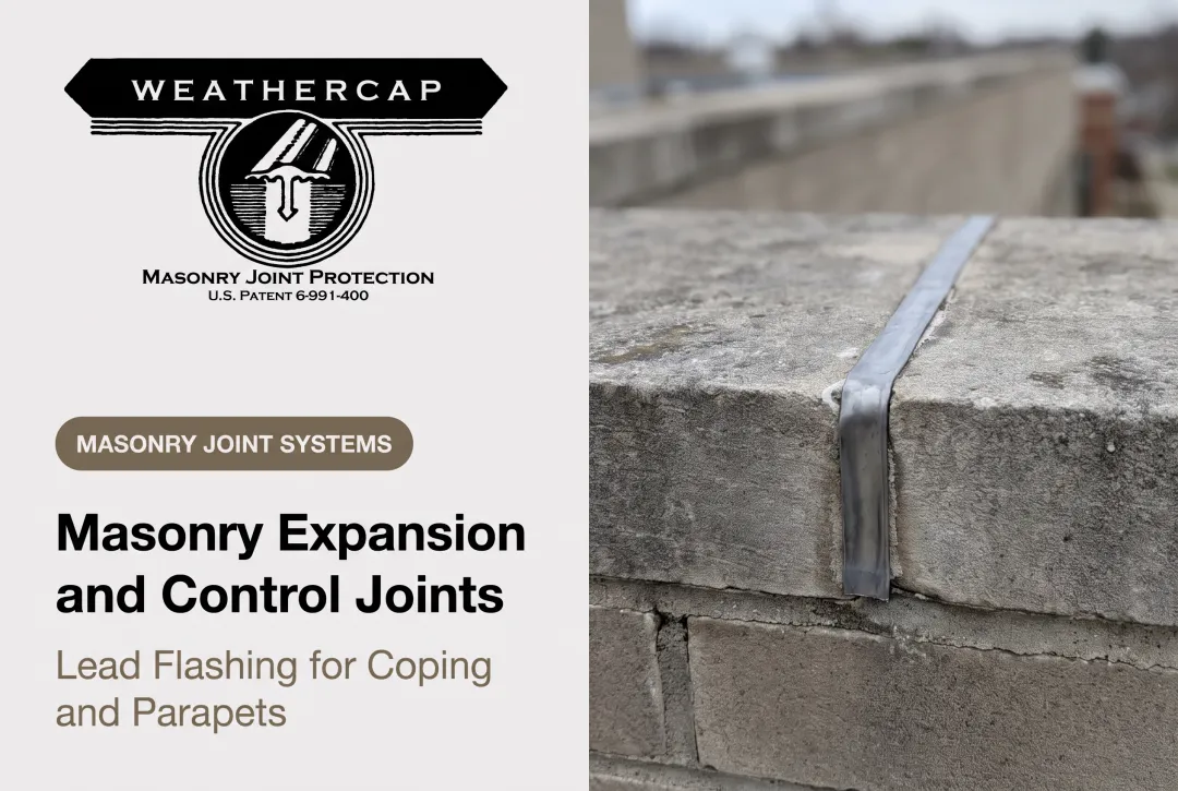
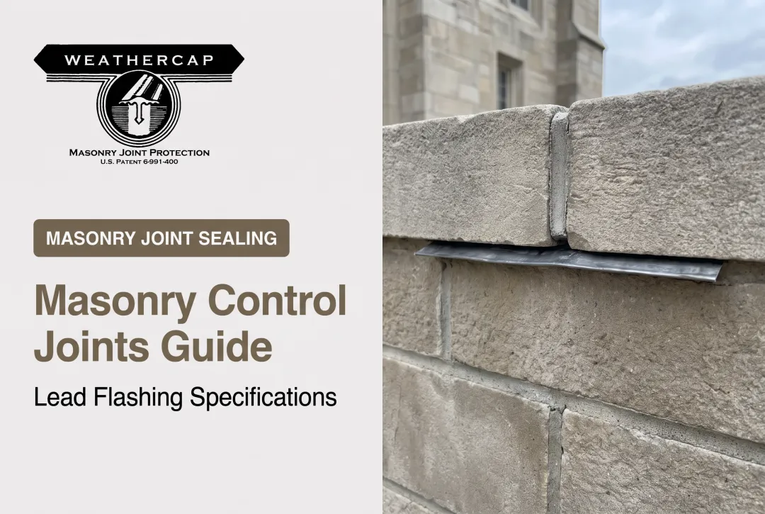
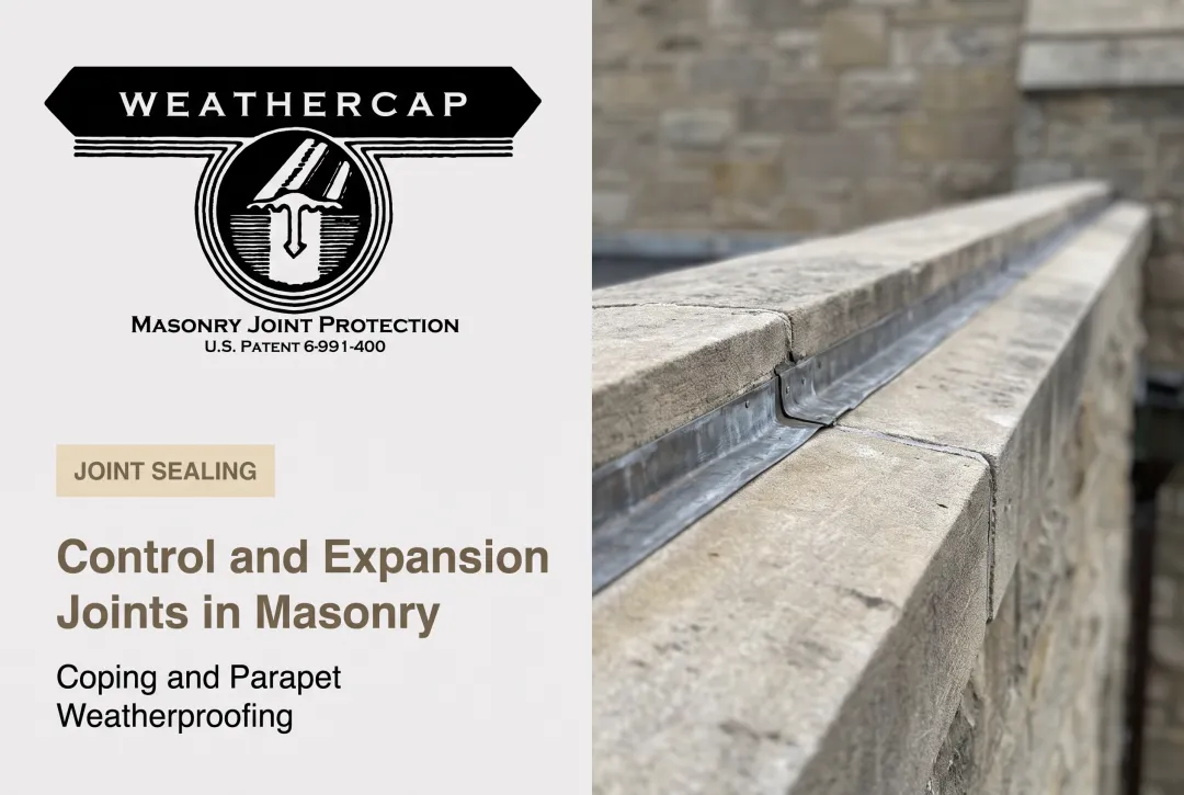
Weathercap's patented soft lead strip system closes that gap. It places a soft lead cap in the sealed masonry joint and reduces the opening the sealant must span. Set into a void-free sealant bed, the strip lets sealant bond around the cap instead of bridging the full joint width, cutting the exposed opening by roughly half.
The lead itself does the heavy lifting during movement. Its low tensile strength, low hardness, and low elastic modulus let it creep into a new configuration as the joint opens and closes, rather than tearing under stress the way sealant alone eventually does.

Weathercap's track record includes work at the Washington Monument, U.S. Supreme Court, and Smithsonian Institution, and the system is specified by name in the GSA Historic Preservation Technical Procedures (Document 07656-01) under "Installing Lead Stone Flashing to Protect Masonry Joints." That specification bar matches what control joints need: protection that stays in place for decades of movement.
For control joints, those durability traits show up in day-to-day performance:
- Resists tearing and shearing under repeated joint movement
- Oxidizes to a neutral grey that blends with most masonry
- Accepts paint when facade color matching matters
- Covers the sealant so UV and weather hit the cap first
Type A (flat cap) and Type B (90° cove cap) cover openings from about 5/16 in. to 1.5 in.—most CMU and cast stone control joints. Strips ship in 6-foot lengths within 48 hours, sized to the joint opening, anticipated movement, and a ¼-inch allowance.
Frequently Asked Questions
Are control joints required by code?
Codes like the IRC require control joints in specific slab conditions (such as flood-zone breakaway slabs) at defined spacing, but there's no blanket national IRC rule for ordinary slabs. Masonry standards from NCMA and BIA call for control joints too, though exact requirements vary by jurisdiction.
Does a 10x10 concrete slab need control joints?
Using common industry spacing ranges, a 10 ft panel on a typical 4-inch slab often falls within recommended limits without an interior joint. Shrinkage risk, mix design, and reinforcing conditions can still change that answer for a specific project.
What's the difference between a construction joint and a control joint?
A construction joint marks a planned stop in concrete placement and carries continuous rebar through it. A control joint is an intentional weak plane designed to guide where cracking happens, with nonstructural reinforcing discontinued at the joint.
How deep should a control joint be on a concrete slab?
ACI guidance generally calls for a saw cut of about one-quarter of the slab thickness, per ACI 327R-14. Early-entry saws can achieve the intended effect at a shallower depth.
What happens if control joints are installed incorrectly?
Continuous reinforcing crossing the joint, or joints stopped short of the wall base or above lintels, prevent the joint from opening as designed. The result is random cracking elsewhere in the wall and a higher risk of water infiltration.