
Building Science Corporation has documented this pattern for years: metal and stone copings leak at joints, not through the metal or stone itself. That's a small detail with an outsized cost. A failed coping joint can sit unnoticed for months, quietly rotting sheathing, staining ceilings, and corroding embedded steel before anyone finds it.
This article breaks down what parapet cap flashing actually is, the types available, why joints fail even when the cap material is sound, and what a proper detail requires. Whether you're specifying new construction or restoring a 100-year-old masonry facade, the same joint-level principles apply.
Key Takeaways
- Coping joints, not the flashing material, cause most parapet leaks
- Material choice (aluminum, steel, lead, membrane) affects lifespan and movement tolerance
- Overhangs, drip edges, and joint protection matter more than the cap alone
- Post-storm and post-roofing-work inspections catch failures before they become structural
What Is Parapet Wall Cap Flashing?
Parapet flashing is a broad category covering every waterproofing component at the roof-to-wall transition. Cap flashing, sometimes called coping, is the specific piece that covers the top of the parapet wall itself.
Here's the distinction that trips people up: flashing at joints and terminations redirects water, while cap flashing (coping) covers and protects the top surface of the wall. Per a 2016 Construction Specifier article on masonry-roofing interfaces, the parapet is the rising wall built above the roof line—and it needs a different waterproofing strategy than the vertical wall below it.
Cap flashing doesn't work alone. It integrates with:
- Base flashing — turns up from the roof membrane onto the parapet's inner face
- Counterflashing — covers the top edge of base flashing to shed water
- The roof membrane — should run continuously under the coping, not stop short of it
Building Science Corporation (BSC) is explicit on that last point: skip membrane continuity under the coping, and you've built in a failure point before the cap ever goes on.
The 2021 International Building Code backs this with a hard requirement — parapet walls must be coped or covered, and the top surface must provide positive drainage (IBC Sections 1503.3.1 and 1503.3.2).

Types of Parapet Flashing and Cap Configurations
Four categories cover most parapet conditions. Each one handles a different part of the same job: keeping water out of the parapet’s core.
- Base flashing — bridges the roof membrane up onto the parapet wall
- Counterflashing — caps and protects the top edge of the base flashing
- Coping / cap flashing — covers the top of the wall and sheds water both ways
- Membrane wall flashing — fully adhered or fastened membrane in place of a metal cap
Metal & Coping Cap Types
Metal coping remains the standard for most commercial and institutional parapets. Common options include:
- Aluminum — lightweight, corrosion-resistant, common on new construction
- Galvanized steel — economical, widely specified
- Stainless steel — higher upfront cost, longer service life in harsh climates
- Lead — traditional choice for historic masonry, still specified in restoration work
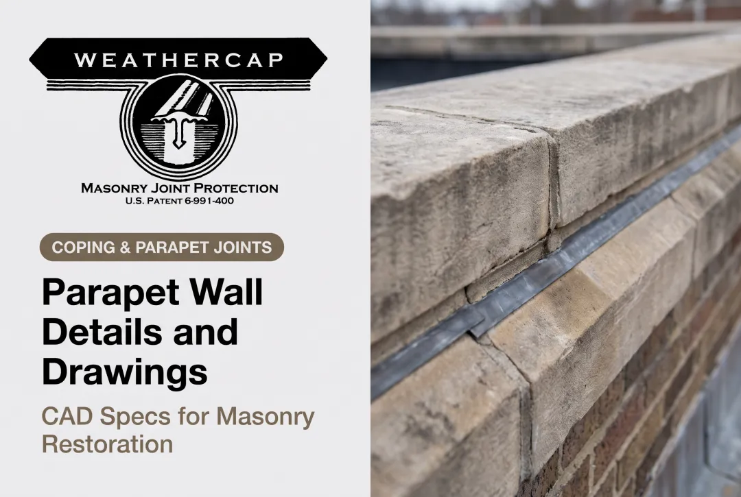
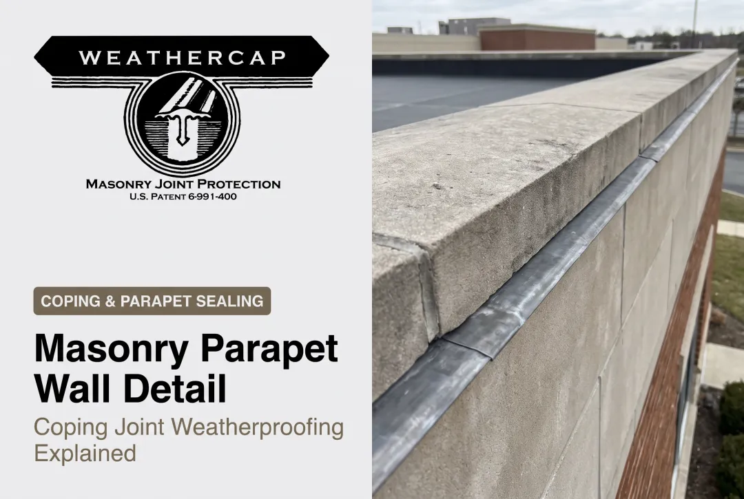
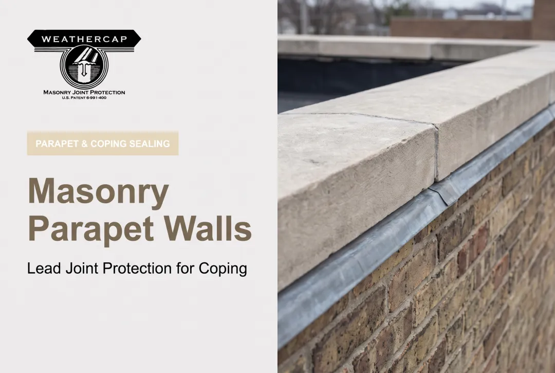
NRCA's 2005 Professional Roofing manual illustrates six distinct methods for installing sheet-metal parapet caps, traditionally shown with a joint cover plate at seams. That cover plate matters: it is usually the weakest point in the entire cap assembly. Coping and cornice joints still move with the building, so the metal cap alone is not the full weather seal—joint protection at those seams (including soft lead joint caps on masonry copings) is what keeps water from tracking into the wall core.

Membrane-Based Flashing
Membrane wall flashing is an alternative to metal coping, particularly where the parapet detail calls for a fully adhered or mechanically fastened waterproofing membrane instead of a metal cap. The choice between metal coping and membrane flashing tends to depend on:
- Climate exposure and freeze-thaw frequency
- Whether the project is new construction or historic restoration
- Existing masonry condition and joint geometry
There is no universal wall-height rule that dictates metal coping versus membrane flashing. Some contractors cite informal 24–48 inch thresholds, but no code body or manufacturer standard locks that in. Choose the detail from exposure, masonry condition, and how the joints will move—not from a single height number.
Why Parapet Cap Flashing Fails (and How Joint Protection Prevents It)
Here's the part most spec sheets gloss over: the metal or stone rarely fails. The joints do.
Building Science Corporation (BSC) research is blunt: metal and stone copings leak at joints, and a missing membrane under the coping is a documented failure condition. Add thermal cycling and freeze-thaw stress, and a coping can look fine from the ground while water enters above.
The Sealant Problem
Caulk and sealant joints are the default gap-filler at coping seams, corners, and terminations. They degrade for two reasons:
- Joint size and spacing mismatches — a 2018 Construction Specifier piece notes that sealant failure is often caused by joint geometry, not the sealant itself
- Adhesion loss at the bed joint — a 2023 follow-up article documents adhesion failure specifically at coping bed joints
Sealant alone isn't designed to absorb ongoing building movement indefinitely. It's built to seal a static gap, and parapets rarely stay static.
Joint Protection as a Second Layer
This is where a joint protective system earns its place. WEATHERCAP's patented soft lead strip sits within the sealant joint rather than replacing it. Two lead properties make this work:
- Low creep strength — lets the lead physically creep into a joint's new shape after movement, instead of tearing
- Low elastic modulus — allows this accommodation to continue indefinitely within the joint's design limits
Interposed between sealants, the strip physically reduces the effective masonry-joint opening by half. It also caps the sealant itself, shielding it from the surface stress and abrasion that typically cause margin checking at coping and right-angle wall junctions. That is the same geometry where a cornice or belt course meets a parapet.

This isn't a niche approach. It's specified in GSA Document No. 07656-01, the U.S. General Services Administration's Historic Preservation Technical Procedures, under "Installing Lead Stone Flashing to Protect Masonry Joints."
That procedure covers parapets, copings, balustrades, and cornices: the exact conditions where joint-level protection outperforms sealant alone. The same system has been used on restoration work at the Washington Monument, the U.S. Supreme Court Building, the Smithsonian, and the U.S. Treasury Building.
Thermal cycling and freeze-thaw don't cause the initial crack. They compound whatever weakness already exists at the joint, widening small gaps into leak paths season after season. Capping the surface isn't enough if the joint underneath keeps moving unchecked.
Key Components of a Proper Parapet Cap Flashing Detail
A cap flashing detail is only as good as its weakest dimension. Four elements decide whether water sheds cleanly or tracks back into the wall:
- Overhang: the cap must extend far enough past the face to drip clear of the facade, not run down it
- Drip edges front and back: Building Science Corporation (BSC) specifically calls for drip edges on both faces to prevent facade staining and water tracking back under the flashing
- Expansion joints: metal coping needs standing seams or continuous cleats to absorb thermal movement without buckling
- Continuity: the waterproofing membrane, coping, and wall cladding need to connect without gaps or overlaps that trap water
For lead strip joint protection specifically, installers should:
- Install in full 6-foot lengths where possible
- Turn down a minimum of 1 inch over front and back faces at ledges and copings, or extend to the drip edge
- Overlap joint edges by at least 1/8 inch
- Size the strip to the joint opening plus anticipated movement, plus a 1/4 inch allowance
Type A (flat cap) configurations are typically used at the top, side, and cross joints of copings and balustrades. Type B, with its 90-degree cove profile, is specified where a cornice, belt course, or water table meets a parapet at roughly a right angle. That geometry concentrates stress and is hard to seal with caulk alone.

Warning Signs and Maintenance Best Practices
Catching a joint failure early is far cheaper than replacing an entire coping run. Watch for:
- Water stains on the parapet face below the coping line
- Efflorescence: white mineral deposits signaling moisture moving through masonry
- Cracked or separated coping joints that open a path for water into the wall
- Rust stains streaking down from metal fasteners or cap seams
- Interior ceiling stains near exterior walls, often the first sign anyone actually notices
Inspect after:
- Major storms or high-wind events
- Any roofing work performed nearby (foot traffic and material staging often disturb coping seals)
- Routine building-envelope maintenance cycles
NRCA advises owners to assess storm damage from the ground and avoid unsupervised repairs (a fall risk best left to trained crews). Fix sealant-level failure early—waiting turns a maintenance line item into a full coping replacement.
Parapet Wall Safety Considerations
OSHA Requirements for Parapet Walls
Any work near a parapet edge triggers fall-protection rules. Under 29 CFR 1926.501, OSHA requires one of the following whenever a worker is on an unprotected edge 6 feet or more above a lower level:
- Guardrails
- Safety nets
- Personal fall-arrest systems
For low-slope roofing work, OSHA also permits warning-line combinations or a safety-monitoring system under specific width conditions.
These thresholds apply regardless of coping material or joint detail. Confirm current OSHA standards before flashing work begins. Requirements are periodically updated.
Frequently Asked Questions
What is parapet flashing?
Parapet flashing refers to the waterproofing components: base flashing, counterflashing, and cap flashing — that protect the roof-to-wall transition where a parapet meets the roof membrane.
What are the types of parapet flashing?
The main types are base flashing, counterflashing, cap/coping flashing, and membrane wall flashing. Each addresses a different part of the parapet's water-shedding path.
What is parapet cap flashing (parapet capping/coping)?
It's the protective covering on top of the parapet wall that sheds water away from the face below. It can be metal, stone, or membrane-based, depending on the project.
What flashing is used where a roof meets a wall?
Base flashing turns up from the roof membrane onto the wall, while counterflashing covers its top edge to keep water from getting behind it. Together they seal this critical transition.
What are parapet flashing details?
These are the drawings and specifications showing how the membrane, insulation, coping, and joint protection integrate at the parapet. They're essential references for contractors during installation.
What are the OSHA requirements for parapet walls?
OSHA requires fall protection — guardrails, nets, or personal fall-arrest systems — for work on unprotected edges 6 feet or more above a lower level. Always verify current OSHA standards before starting flashing work.