
Ignore that need, and you get cracked block, bowed brick veneer, and sealant that fails years ahead of schedule. Get it right, and a masonry facade can last decades with minimal intervention.
This article breaks down the difference between control joints and expansion joints, how to place and space them correctly, and how to protect the sealant that does the real work once the joint is cut.
TL;DR
- Control joints manage shrinkage in CMU walls; expansion joints accommodate growth in clay brick veneer. They are not interchangeable.
- Both prevent cracking, water intrusion, and premature masonry failure.
- Correct spacing, placement, and sealant protection determine long-term performance.
- Many masonry "failures" trace back to missing or misplaced movement joints, not bad materials or workmanship.
What Are Control and Expansion Joints in Masonry?
Control joints are vertical or horizontal separations built into CMU (concrete masonry unit) walls. Concrete masonry shrinks as it cures and dries. A control joint gives that shrinkage a designated place to happen instead of letting cracks form randomly across the wall.
Expansion joints serve the opposite purpose in clay brick veneer. Clay units absorb moisture and expand — sometimes permanently — over their service life. An expansion joint is a compressible gap that lets brick grow without spalling, bowing, or displacing coping stones.
The Masonry Society's TMS 402-22 code uses "movement joints" as an umbrella term covering both. That's useful shorthand, but don't let it blur the distinction on your drawings:
- Concrete masonry shrinks → needs control joints
- Clay brick expands → needs expansion joints
These joints are engineered features. Size and locate them on structural drawings and elevations before a single block gets laid.

Why Movement Joints Are Critical in Masonry Construction
Masonry expands, contracts, and settles constantly in response to temperature, moisture, and load. Left unmanaged, that movement finds its own path — usually straight through a mortar joint or a brick face.
Brick Industry Association Technical Note 18A puts it plainly: the type, size, and placement of movement joints are critical to how the wall performs over its lifespan (BIA Technical Note 18A). Skip that step, and consequences stack up fast:
- Water infiltration behind the veneer
- Mold and moisture damage inside wall cavities
- Accelerated sealant degradation
- Expensive repairs, especially on historic or high-value structures
Here's the part designers sometimes miss: TMS 602 assigns the responsibility for locating movement joints to the designer, not the mason on site. The code requires project drawings to indicate the type and location of movement joints directly (TMS 402-22). A generic spec note saying "provide movement joints as needed" doesn't meet that bar.
The International Masonry Institute has observed that most cracking problems trace back to missing or poorly detailed movement joints — not bad materials or sloppy work. That matches what shows up in the field.

Control Joints vs. Expansion Joints: Key Differences
These two joint types solve different problems. Treating them as interchangeable is where a lot of design errors start.
Control Joints (CMU Walls)
Control joints interrupt horizontal reinforcement so the block can shrink without transferring stress across the joint. If reinforcement runs straight through, it pins the wall together and defeats the joint's purpose.
- Best suited for: long CMU walls, structural or back-up walls, warehouses, schools, retail buildings
- Key strengths: reduces shrinkage cracking, straightforward to install, cost-effective
- Limitations: placing them too close to openings can cut into shear wall capacity. Coordinate with a structural engineer before finalizing locations
Expansion Joints (Clay Brick Veneer)
Expansion joints use compressible filler and sealant to absorb clay brick's growth over time. They protect the wall and stop parapet copings and stone from getting pushed out of place.
- Best suited for: brick veneer facades, cavity wall systems, tall or long veneer runs, historic masonry restoration
- Key strengths: prevents bowing, spalling, and displaced coping/parapet stones
- Limitations: sealant alone tends to fail early. Building movement, UV exposure, and moisture cycling all work against a caulk joint sitting exposed on its own.
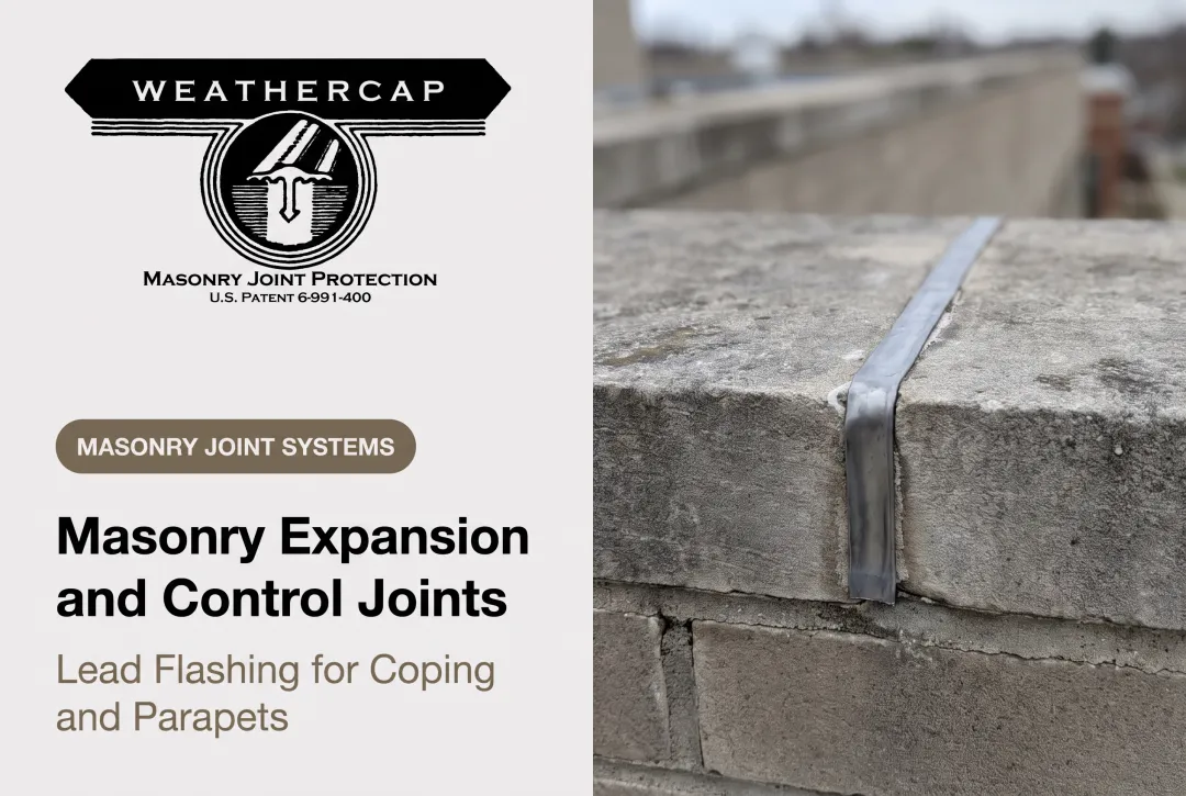
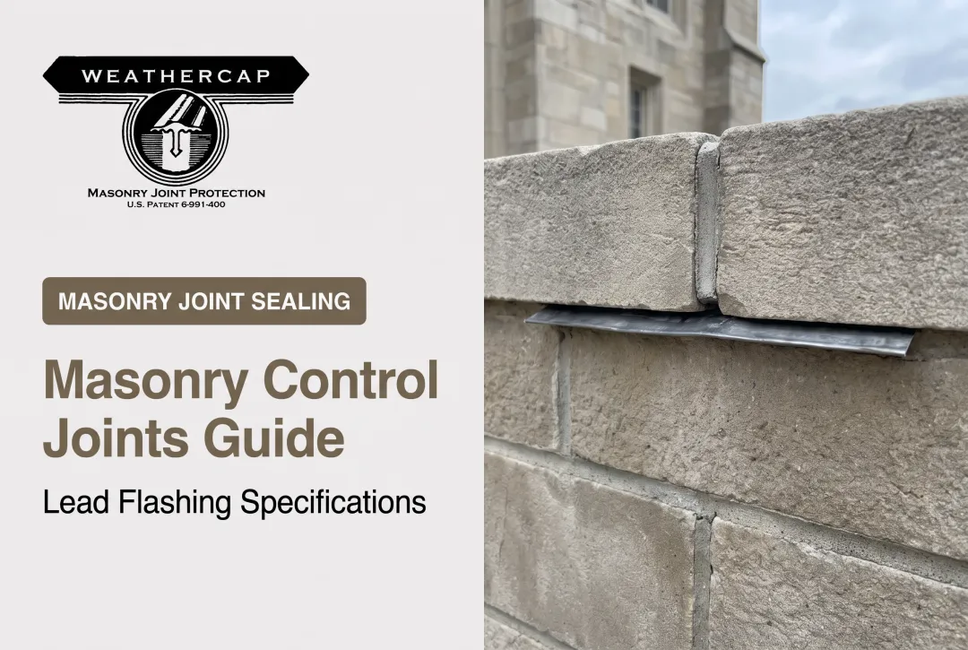
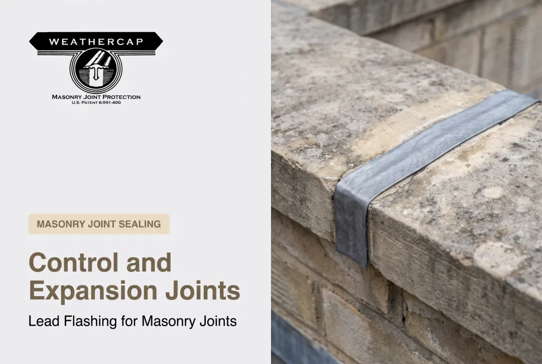
That last limitation is where supplemental protection earns its keep. Weathercap's patented soft lead strip sits within the sealed joint, buffering the sealant against movement rather than leaving it to absorb stress alone.
The strip has low creep strength and a low elastic modulus, so it deforms into the joint's new shape after movement instead of tearing or shearing. That cuts the opening the sealant must bridge by roughly half and extends how long the seal lasts.

How to Determine Joint Placement and Spacing
Spacing isn't a single number you can memorize. It depends on the material, the wall geometry, and the environment.
CMU Control Joint Spacing
CMHA's 2025 crack-control guidance sets an empirical length-to-height ratio limit of 1.5:1. Maximum spacing is capped at 25 ft 4 in for standard 8-inch units and 20 ft for 4-inch units or concrete masonry veneers (CMHA Tech Note CMU-TEC-009-25). Tighter spacing may still be required based on exposure, openings, and structural role.
Brick Expansion Joint Spacing
BIA recommends no more than 25 ft on center for brickwork without openings, tightening to 20 ft on center where there are multiple openings (BIA Technical Note 18A).
Factors That Shift These Numbers
- Wall length and height relative to the panel ratio limits above
- Openings and corners — place joints within about 2 ft of a corner (BIA)
- Structural role — shear walls behave differently than non-structural veneer panels
- Climate and moisture — exposure and seismic demand can tighten spacing
- Material type — CMU, clay brick, and mixed assemblies each need their own logic
- Long-term access for inspection and resealing

Common Mistakes and What to Check Before Finalizing Joint Design
Most movement joint failures trace back to a handful of repeat offenders. Check for these before signing off on a design:
- Generic spec language instead of drawn locations. "Provide control joints as required" isn't a location. Show joints on elevations, with dimensions.
- Control joints too close to lintels or openings. This weakens shear capacity right where the wall needs it most. Coordinate placement with the structural engineer, not just the mason.
- Reinforcement running through the joint. If horizontal reinforcement crosses a control joint uninterrupted, it restrains the exact movement the joint was designed to allow.
- Undersized expansion joints. BIA's formula, Se = (wj × ej) / 0.09, ties spacing to joint width and sealant compressibility. Undersize the joint, and you get over-stressed sealant, backer rod failure, or bowed brick.
- Skipping supplemental protection at high-stress points. Copings, parapets, and right-angle wall junctions take the brunt of building movement. This is where an unprotected caulk joint fails first.
At those high-stress locations, product configuration matters:
| Location Type | Recommended Configuration |
|---|---|
| Right-angle wall junctions (parapet/side wall meeting) | Type B 90° cove cap |
| Flat coping runs, balustrade joints | Type A flat cap |
Weathercap's installation guidance calls for the lead strip to sit entirely within the sealant bed — never touching the backer rod or masonry directly.
Backer rod is seated ¼ inch below the anchor shaft tip, leaving a sealant buffer between them. Skip that detail, and direct contact between the strip and backer rod can undercut the flexible seal you were trying to create.

Conclusion
Control joints and expansion joints solve different problems, but they share the same goal: giving masonry room to move without cracking or leaking. Correct placement, correct spacing, and long-term sealant protection are what separate a facade that lasts decades from one that needs restoration within a few years.
Those same requirements show up on high-stakes work. Weathercap's lead strip system has been specified on projects like the Washington Monument, the U.S. Supreme Court Building, and the Smithsonian Institution, where premature caulk failure is not an option and joint details have to hold up for the long term.
Frequently Asked Questions
What is a control joint in masonry?
A control joint is a vertical or horizontal separation in a CMU wall that relieves shrinkage stress. It gives the wall a planned location to move instead of cracking randomly.
Do masonry walls need control joints?
Most CMU walls need them. Concrete masonry shrinks as it cures, and without a designated relief point, that shrinkage shows up as unplanned cracking.
How far apart should control joints be in CMU walls?
CMHA guidance caps spacing at roughly 20-25 feet depending on unit height, with a 1.5:1 length-to-height ratio limit. Exact spacing depends on wall geometry and openings.
What is the purpose of an expansion joint in masonry walls?
Expansion joints let clay brick veneer expand from moisture and heat without spalling, bowing, or pushing coping stones out of alignment. They're a compressible gap, not a structural crack.
How wide should an expansion joint be in a brick wall?
BIA recommends a typical width of 3/8 to 1/2 inch, with sealant depth around half the joint width (minimum 1/4 inch). Undersizing leads to over-stressed sealant and premature failure.
How long can a brick wall be without an expansion joint?
BIA guidance caps spacing at 25 feet without openings and 20 feet where there are multiple openings. Climate, height, and structural conditions can tighten that further.