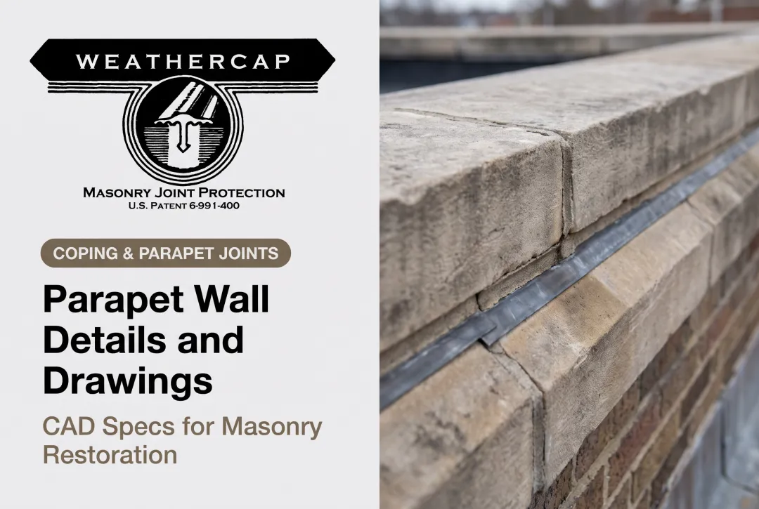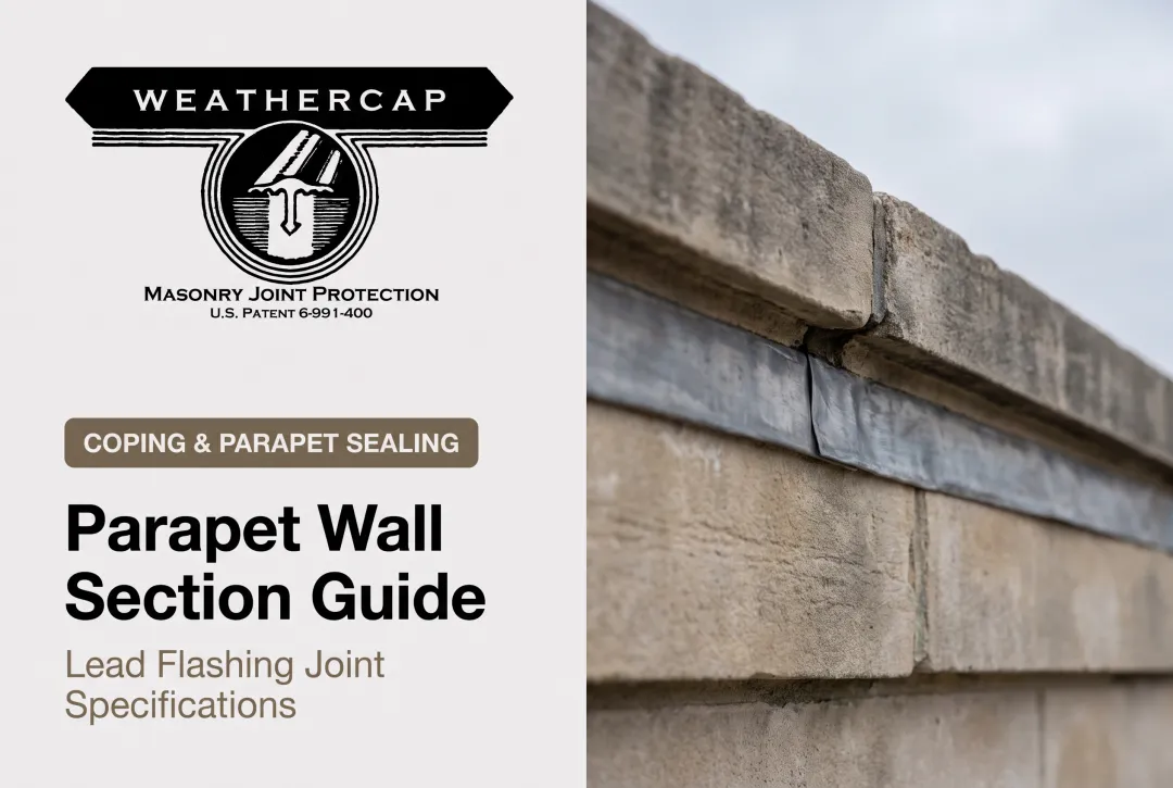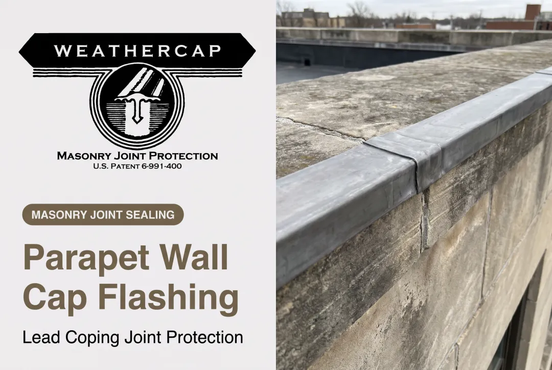

This guide covers the anatomy of a masonry parapet detail, the IBC minimums that govern height and thickness, where these assemblies typically fail, and how to protect the sealant joints that do most of the heavy lifting. Getting the coping right matters. Protecting the joints beneath it matters just as much.
Key Takeaways
- Parapet details must run structural, waterproofing, and thermal layers continuously from roof to wall
- IBC height rules differ: 30 inches for fire-rated parapets, 42 inches for guards; the two are not interchangeable
- Coping and sealant joint failures cause most parapet-related water infiltration
- Shielding sealant joints from UV, movement, and weathering extends the life of the full parapet assembly
What Is a Masonry Parapet Wall Detail?
A masonry parapet is simply an extension of the exterior wall above the roofline. Historically, parapets served defensive purposes; the word traces back to Italian roots meaning "to guard the chest." Today they serve three primary roles at the roof edge:
- Fire separation between structures or roof areas
- Fall protection for anyone working at height
- Weatherproofing where the wall meets the roof
When that extension is built in brick, the assembly gets more specific. A brick parapet uses brick masonry wythes rather than concrete masonry unit (CMU) or poured concrete. Older brick parapets were often multi-wythe assemblies — interior, middle, and exterior layers bonded with mortar-filled collar joints. This construction method is durable but unforgiving: without continuous flashing and movement joints, differential expansion between wythes cracks the assembly from the inside out.
The "detail" itself is the drawing or specification showing exactly how coping, flashing, membrane, and cladding interconnect at this transition. It ranks among the most failure-prone conditions in construction because a two-dimensional drawing has to resolve a complex, three-dimensional geometry problem.
Well-detailed parapets have protected landmark buildings across the U.S. for over a century. When the wall-to-roof transition fails, repairs are rarely cheap.
Parts of a Parapet Wall
A parapet detail is only as strong as its weakest component. According to BIA Technical Notes 21B, the core parts include:
- Coping/cap — the horizontal cover protecting the top of the wall
- Through-wall flashing — collects moisture that penetrates the exterior wythe and diverts it outward
- Cladding (face brick or veneer) — the visible exterior finish
- Structural backup — CMU or brick wythes carrying structural loads
- Sealant joints — flexible connections accommodating movement
- Drip edges — projections that shed water away from the wall face

How those parts are assembled matters as much as the parts themselves. In older masonry parapets, the cavity between wythes should continue all the way to the top so the inner and outer wythes can move independently. Expansion joints need to run through as well. Skip this, and you get restrained movement that shows up later as step cracking or bowing.
Coping: The First Line of Defense
Coping takes the brunt of weather exposure, so slope and drip edges aren't optional design flourishes. BIA specifies coping should slope toward a drip and include a drip edge on at least one side.
Transverse joints between coping units (the seams running across the top of the wall) are one of the most common leak sources in the entire assembly. Water finds these seams and works its way in over years of freeze-thaw cycling.
Building Code Requirements & Standard Dimensions
The International Building Code is the model code most U.S. jurisdictions adopt, though local amendments can tighten these requirements. Two height numbers get mixed up constantly.
Height requirements aren't one-size-fits-all:
| Requirement | Code Section | Minimum |
|---|---|---|
| Fire-related parapets | IBC 2021 §705.11.1 | 30 inches above the roof-wall intersection |
| Guards (fall protection) | IBC 2021 §1015.3 | 42 inches above the walking surface |
A guard is triggered when a walking surface drop exceeds 30 inches, or when a roof hatch sits within 10 feet of a roof edge. These are two separate code questions — a parapet satisfying the fire-rating minimum doesn't automatically satisfy the guard height requirement, and vice versa.
Thickness follows the design method adopted from TMS 402, factoring in wind load, height, reinforcement, and local amendments. There's no universal 8-inch rule that applies across every project. Thickness is engineered, not looked up in a table.
Wind loads matter more than most designers expect. Per ASCE 7-16 §27.5.2, parapets face specific wind-pressure provisions within the main-wind-force-resisting-system calculations. Taller or thinner parapets often require steel reinforcement or pilasters to resist wind-driven overturning forces. Treat height, thickness, and reinforcement as project-specific engineering outputs, not fixed dimensions you can copy from a previous job.
Common Failure Points in Masonry Parapet Details
Parapets fail predictably, and the mechanisms repeat across nearly every building type.
- Mortar joint deterioration: Thermal movement and freeze-thaw cycling crack and soften mortar joints over time. Cracking is usually a symptom of a bigger problem underneath, not an isolated cosmetic issue.
- Sealant joint failure: Caulk and sealant at copings and wall junctions fail when they can't accommodate ongoing building movement. UV exposure and material fatigue push joints that looked fine at installation into failure within a few years.
- Rust-jacking: This one sneaks up on building owners. Corroding steel anchors expand as they rust, and that expansion cracks or displaces the surrounding masonry—sometimes dramatically. Stainless steel anchors resist this corrosion and are now the preferred choice for coping attachment.
- Discontinuous control layers: When air, vapor, and moisture barriers don't connect continuously between the roof membrane and the wall assembly, you get chronic leakage that's maddeningly hard to trace. The gap is often invisible until water appears far from where it entered.

A quick self-check: if you're seeing displaced coping, step cracking, or staining below a parapet, don't assume it's just a resealing job. Inspect the anchors, joint movement capacity, and control-layer continuity before you specify a fix.
Protecting Sealant Joints for Long-Term Performance
Here's the uncomfortable truth: even a perfectly detailed parapet fails prematurely if nobody protects the sealant joints at copings and wall junctions. Sealants should last 20 or more years, but in documented laboratory testing, nearly 29 percent of specimens had already failed after just the first accelerated test round.
UV exposure, joint movement, and weathering wear sealant down faster than most specifications assume. That's the exact problem Weathercap's patented soft lead strip system was built to solve.
Interposed within a sealed masonry joint, the lead strip absorbs movement stress and reduces the effective joint opening by about half, while physically covering and protecting the sealant beneath it from UV and weather exposure.
Two configurations match different parapet conditions:
- Type A Flat Cap: for horizontal joints atop copings and balustrades, extending across the top and down the parapet face
- Type B 90° Cove Cap: for right-angle wall junctions, such as where a cornice, belt course, or water table meets a parapet or side wall

The system is specified in the GSA's Historic Preservation Technical Procedures for exactly this application. It has been installed on buildings including the Washington Monument and the U.S. Supreme Court, structures where a resealing callback every five years simply isn't an acceptable outcome.
Because the strip is 99.9% lead, its low elastic modulus lets it creep into a new shape as the building moves, rather than cracking or tearing. The surface oxidizes to a dead neutral grey that blends with surrounding masonry and can be painted, which matters on historic structures where visual authenticity is non-negotiable.
Frequently Asked Questions
What are the building code requirements for parapet walls?
The IBC governs parapet height, thickness, structural stability, and wind resistance, but local jurisdictions can impose stricter amendments. Always check both the model code and local adoption before finalizing a detail.
What is the minimum height required for a parapet?
IBC 2021 sets 30 inches for fire-rated parapets under Section 705.11.1, and 42 inches when guard provisions apply under Section 1015.3. Which one applies depends on occupancy and the specific roof-edge condition.
What is the minimum thickness required for a parapet wall?
There's no universal minimum thickness in the IBC. Thickness follows the adopted masonry design method (TMS 402) and scales with height, wind exposure, and reinforcement.
What are the standard dimensions for a parapet wall?
There isn't a true "standard" size. Dimensions are engineered per project based on wind load calculations, material choice, and local code requirements.
What are the parts of a parapet?
Core components include:
- Coping
- Through-wall flashing
- Cladding (face brick or veneer)
- Structural backup
- Sealant joints
Each plays a distinct role in keeping water out.
What is a brick parapet?
A brick parapet is built with brick masonry wythes rather than CMU or concrete. It offers strong durability but cracks and leaks without proper flashing and joint detailing.