
A lintel is simple in concept: a horizontal structural member that spans an opening and carries the load above it down to the jambs. But "simple" doesn't mean "forgiving." Get the bearing length, reinforcement, or flashing wrong, and you're signing up for repairs down the road.
This article covers lintel types, span and bearing rules, the steel-versus-masonry debate, and the flashing details that keep water out of your wall long after the ribbon-cutting.
Key Takeaways
- Size lintels by span, load, and bearing so opening loads transfer cleanly to jambs and piers
- Choose reinforced masonry over steel when movement, corrosion, or arching action governs
- Set bearing length and rebar placement to control cracking and deflection
- Detail flashing with end dams and weep holes to keep water out of the opening
What Is a Masonry Lintel and Why Design Detail Matters
A lintel sits above every door, window, and vent opening in a masonry wall, carrying the weight of everything above it (brick, block, and floor loads) down to the piers on either side. Without one, that opening simply can't exist structurally.
Here's the problem: many failures don't come from picking the wrong lintel material. They come from getting the detail wrong. Bearing length, reinforcement placement, and flashing decisions matter as much as the size of the beam itself.
The Brick Industry Association's Technical Note 31B is direct about this: many cracks over openings result from excessive lintel deflection caused by improper or inadequate design, not from a lintel that was simply "too small."
BIA limits deflection to the lesser of span/600 or 0.3 inches under combined dead and live loads. Miss that threshold and cracking follows, even if the lintel technically "holds."
Common Consequences of Poor Lintel Detailing
Skip the details, and you'll likely see:
- Diagonal cracking at opening corners from excessive deflection
- Water intrusion through discontinuous or missing flashing
- Staining below openings from water tracking down the facade
- Efflorescence where rainwater dissolves soluble salts and carries them to the surface

None of these show up immediately. They show up in year three or five, once movement and moisture cycles have done their work.
Types of Masonry Lintels
Not every opening needs the same lintel. BIA 31B identifies four primary alternatives for brick masonry construction: reinforced brick masonry, brick masonry arches, precast concrete, and structural steel shapes.
Plain vs. Reinforced Brick Lintels
Plain (non-reinforced) brick lintels and arches work for short spans with light loads, relying on compression and geometry rather than steel. Reinforced brick lintels embed steel bars in the mortar joints, adding tensile capacity that plain masonry can't provide on its own. This lets you span farther and carry more load.
Precast vs. Cast-in-Place CMU Lintels
Reinforced concrete masonry (CMU) lintels are available in two forms:
- Precast: fabricated off-site, cured, then set in place. Faster installation, consistent quality control.
- Cast-in-place: grouted and reinforced on-site. Better for irregular openings or where matching existing masonry courses matters.
The CMHA/NCMA design manual for concrete masonry lintels covers both approaches under current TMS 402/602 provisions.
Industry Taxonomy vs. BIA’s Brick List
Across general construction, lintels are commonly grouped into four materials: timber, masonry/brick, reinforced concrete, and steel.
BIA’s brick-specific list (reinforced brick, brick arches, precast concrete, steel) sits inside that taxonomy. Timber appears in older or vernacular work, but it falls outside BIA’s brick-masonry framework.
Arch Lintels for Heritage Work
In thick masonry walls, especially on historic buildings, arch lintels use geometry instead of steel. BIA divides these into minor arches (span under 6 feet, rise/span ratio up to 0.15) and major arches beyond those limits. Arches generate horizontal thrust, so the supporting wall must resist that force without yielding at the spring line.
Key Design Considerations: Span, Bearing, and Reinforcement
How Far Can a Lintel Span?
There is no single universal span limit in the 2024 IBC's masonry chapter — it defers to TMS 402/403/404 for actual design requirements. BIA's guidance suggests most codes historically permitted steel angle lintels for openings up to 8 feet, with larger openings typically requiring fire-protected beams or plates. That's guidance, not a hard ceiling — your governing code edition and engineer's calculations decide the actual number.
Bearing Length Requirements
This is where a lot of field cracking actually originates. Insufficient bearing concentrates the reaction load into a small contact area, and masonry handles concentrated point loads poorly.
- CMHA TEK 17-01D uses 4 inches as a typical minimum end bearing in its design examples
- BIA 31B requires no less than 3 inches for structural steel angle lintels, with actual bearing area calculated from reaction force and allowable masonry compressive stress
- The IBC's 4-inch bearing rule (Section 2111.8) applies specifically to fireplace openings — not lintels generally
Don't treat any single number as universal. Bearing length depends on the reaction load, masonry compressive strength, and the applicable code edition.
Should Lintels Be Bedded on Mortar?
Once bearing length is set, bedding is the next contact detail that affects how load transfers into the masonry. CMHA's design tables reference face-shell mortar bedding as their baseline assumption, but no source establishes a blanket "full bed" requirement across every lintel condition. Follow the adopted TMS 602 specification and your project's approved structural documents — this is a detail, not a universal rule.
Reinforcement Placement and Behavior
Where you place the steel changes how the lintel behaves:
- Bottom reinforcement — typical for simply-supported lintels resisting positive bending moment
- Top and bottom reinforcement — used where continuity or fixed-end conditions create negative moment at the supports
- Deflection control — reinforcement choice must also satisfy CMHA's limit of span/600 for lintels supporting unreinforced masonry
CMHA's example designs assume f'm = 1,500 psi masonry with Grade 60 rebar. A 12x8-inch section with a single No. 4 bar might work where arching action is present; without it, you could need a 12x24-inch section instead.
That size swing is why standardized lintel schedules matter: they prevent both oversizing (wasted material) and undersizing (deflection and cracking).

Steel vs. Reinforced Masonry Lintels: Making the Right Choice
Steel lintels are light, quick to install, and can benefit from arching action once the surrounding masonry engages. The Hardy study in Engineering Structures found contact zones covering roughly 20-30% of the span, with the lintel acting partly as a tension tie that resists spreading forces rather than carrying the full moment alone.
But steel comes with trade-offs:
- Masonry and steel expand and contract at different rates, straining the bond and adjacent sealant joints
- Galvanized steel plus periodic maintenance are needed in harsh climates, per BIA
- Continuous flashing with weepholes is required at lintel level in cavity and veneer walls
Reinforced masonry lintels avoid the corrosion and thermal-mismatch issues entirely, and they preserve consistent color, bond pattern, and texture across the wall face. Arching action can reduce demand on the lintel itself, but only when wall height, end bearing, running bond, and lateral resistance conditions are actually met. Assume nothing; verify the conditions.
Where steel still wins:
- Large openings (BIA flags steel beams with plates above roughly 8 feet)
- Heavier superimposed loads
- Veneer support where a lighter install matters more than avoiding thermal mismatch

Detailing for Long-Term Durability: Flashing and Joint Protection
Even a perfectly sized, perfectly bedded lintel will eventually leak if the flashing detail fails. Water enters masonry walls by nature. The detailing question is whether that water gets managed or trapped.
Why Lintel Heads Need Flashing
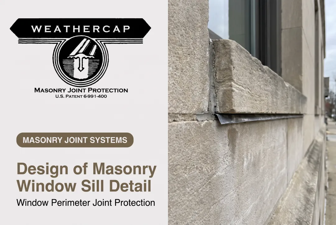
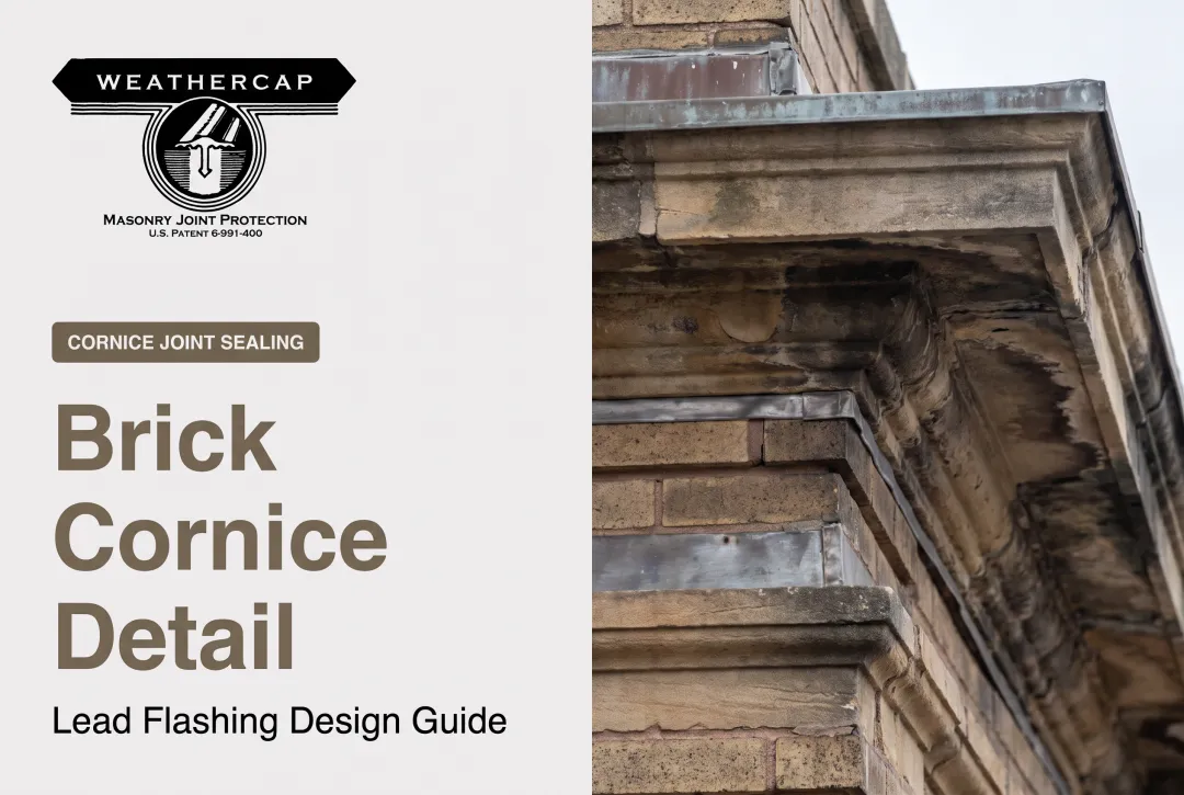
BIA Technical Note 21B requires flashing over and under door and window openings. Where the lintel is discontinuous, flashing must extend past its ends and turn up to form end dams. Otherwise, water simply runs off the flashing edge and back into the wall cavity. Weep holes at the lintel level then give trapped moisture somewhere to exit.
Movement Stresses Sealant Joints Over Time
Buildings move. Thermal cycling, settlement, and seasonal expansion all shift the joints at lintel bearing points and copings. Ordinary caulk doesn't compensate for that movement. It gets stretched and compressed until it fails, a phenomenon sometimes called joint checking. Once the sealant cracks, water has a direct path in.
A Proven Adjunct: Lead Strip Joint Protection
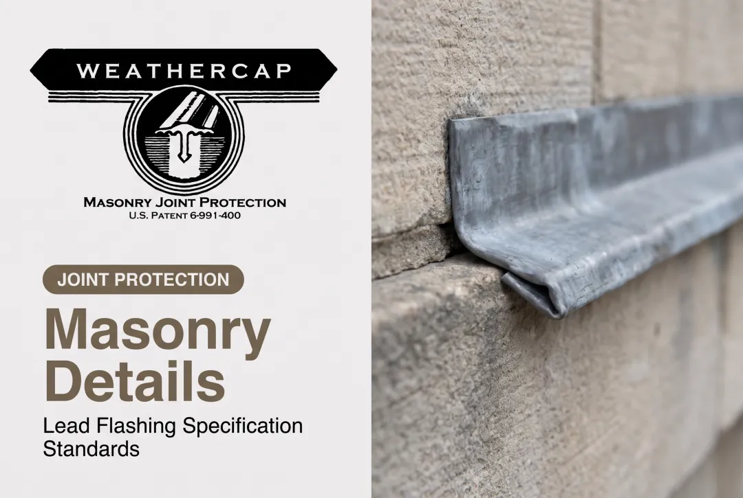
This is where Weathercap's patented lead strip system comes in. Rather than resisting building movement like a rigid material would, the soft lead strip is engineered to creep into the joint's new shape as the building settles or expands. Its low elastic modulus and creep strength let it flex without shearing or tearing. Specify by joint geometry:
- Type A (Flat Cap) is specified for cross-top joints on window and door lintels, as well as coping and balustrade joints
- Type B (90° Cove Cap) is used where a projecting lintel meets a side or parapet wall at roughly a right angle The strip is bedded fully in sealant, with a minimum ¼-inch sealant layer kept between the anchor shaft and backer rod, isolating the system from direct masonry contact and reducing shear risk. Weathercap's own literature notes this approach can reduce the joint opening requiring sealant coverage by about half. Weathercap has been used on restoration projects at the Washington Monument and the U.S. Supreme Court, among other federally significant buildings, and is specified in GSA Historic Preservation Technical Procedures. Extending sealant life at lintel and coping joints means fewer re-caulking cycles and a longer interval before moisture can re-enter the wall.

Frequently Asked Questions
How far can a lintel span?
Span depends on the lintel material, reinforcement, and applied load. Current codes set no single universal limit. Engineered spans typically run a few feet for masonry lintels and considerably longer for steel, governed by TMS 402/403/404 and your project engineer's calculations.
How far should a lintel sit on brickwork?
Minimum bearing commonly runs 3-4 inches depending on the source and lintel type, but the actual required length depends on the reaction load and allowable masonry compressive stress. Always check your governing code edition rather than assuming a fixed number.
Should lintels be bedded on mortar?
Most designs assume face-shell or full mortar bedding for load transfer, but no universal rule applies across every condition. Follow the adopted TMS 602 specification and approved project drawings.
What are the four types of lintels?
The four main types are timber, masonry/brick, reinforced concrete, and steel. For brick masonry specifically, BIA identifies reinforced brick, brick arches, precast concrete, and structural steel shapes.
Why do masonry lintels crack or leak over time?
Excessive deflection can crack the masonry above an opening, while inadequate bearing concentrates stress at contact points. Missing end dams, clogged weep holes, or degraded sealant joints then let water in through gaps that movement opens over time.