
Many designers treat the coping joint as an afterthought. That's a costly mistake. Sealant-only joints crack, water finds its way behind the coping, and masonry restoration bills climb fast. This guide breaks down parapet anatomy, the drawing components that matter, current code requirements, and where these assemblies typically fail.
Key Takeaways
- Parapets need continuous flashing, coping, and joint protection—not a bare masonry cap
- 2024 IBC requires a 30-inch minimum height above the roof line for fire-rated parapets, plus noncombustible-face rules
- Joint protection systems like Weathercap® reduce sealant exposure and extend coping joint life
- Most parapet failures start at coping joints, wall-to-roof transitions, and interior air leaks
What Is a Parapet Wall?
A parapet wall is the portion of an exterior wall that continues above the roofline. It's not just decorative. Parapets serve structural, fire-separation, and aesthetic functions, and on many commercial buildings, they conceal rooftop equipment too.
Three main construction types show up in drawings:
- Masonry parapets — brick or CMU walls extending above the roof, vulnerable at coping joints and mortar cracks
- Framed parapets — wood or steel studs with sheathing, more prone to condensation and rot inside the cavity
- Mixed construction — combines roof deck, framing, and masonry, with the most interfaces to coordinate
Here's the core problem: a normal wall only faces weather from one side. A parapet faces it from the exterior, the interior (roof side), and the top cap. That's why parapets weather faster and fail sooner than the rest of the envelope.

Essential Parapet Wall Components in Construction Drawings
A complete parapet detail drawing isn't just a cap sitting on a wall. It's a stack of interdependent components, each doing a specific job.
Standard components include:
- Coping or cap (metal, stone, or masonry)
- Membrane termination or cant strip
- Counterflashing
- Sheathing and insulation
- Wall assembly and air/vapor barriers
The Coping's Job
The coping sheds water off the top of the wall. It needs to slope inward, sit over a membrane, and include front and back drip edges. The 2024 IBC requires positive drainage and weatherproof coping at least as wide as the parapet itself. Building Science Corporation flags coping joints specifically as a chronic leak point — the joints, not the coping material, are usually where water gets in.
Once the coping sits over the membrane, the next dimension to lock in is how far that membrane runs up the parapet face. Height varies by roofing system rather than a single universal code number. NRCA guidance references an 8-inch base flashing threshold as a design check, so confirm the actual requirement with your roofing manufacturer's system specs rather than assuming a fixed dimension.
Flashing and Termination
At the roof-to-wall junction, the membrane needs a termination bar or fluid-applied flashing to seal against the parapet. Counterflashing then covers that base flashing to shed water away from the seam. FM guidance prefers metal flashing set into a reglet over a termination bar, reserving the bar for situations where cutting a reglet would weaken the existing wall.
Venting in Wood-Framed Parapets
Framed parapets need a moisture-management plan for the cavity. Best-practice guidance calls for high and low vents when the cavity exceeds 12 inches above the roof insulation. Whatever strategy you choose—vented or sealed—call it out on the drawing. An undocumented cavity is a common path to hidden moisture damage.
Reading a Labeled Parapet Section
A typical CAD-style parapet section, top to bottom, should show:
- Coping cap with front/back drips
- Weathercap® or equivalent joint protection at the coping seam
- Membrane termination bar
- Counterflashing over base flashing
- Sheathing and water-resistive barrier (WRB)
- Insulation and air barrier continuation
- Vent holes (if framed and vented)

Weathercap® at the Coping Joint
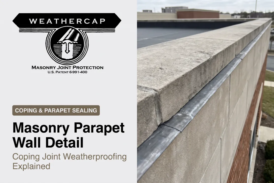
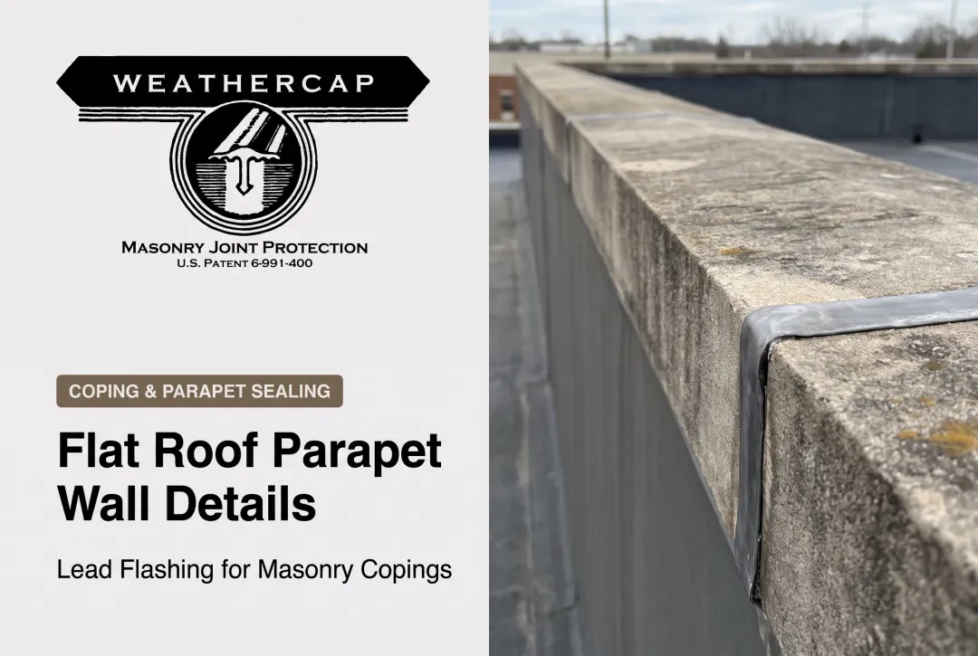
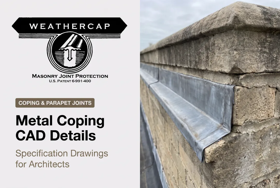
This is where a patented detail component earns its place in the drawing set. Weathercap® is a soft lead strip interposed within the sealant of a coping or masonry joint.
Instead of relying on caulk alone to stretch and crack over years of thermal movement, the lead cap sits bedded in the sealant, buffering stress and cutting the effective joint opening by roughly half.
Installation tolerances to note on the detail:
- Cut the joint for the anchor shaft plus ¼ inch
- Set backer rod ¼ inch below the anchor tip
- Fill sealant to ⅛ inch above the masonry surface, then press in the lead strip

Weathercap ships in 6-foot lengths, with orders shipping within 48 hours.
Because lead has low creep strength and a low elastic modulus, it moves with the joint instead of resisting it. It is specified in the GSA's Historic Preservation Technical Procedures (Document 07656-01), and it has been used on parapet and coping work at the U.S. Treasury Building and Federal Reserve Bank, among other federal and institutional properties.
Parapet Wall Design Considerations
Getting a parapet detail right on paper means accounting for movement before it happens, not reacting to cracks afterward.
Key design factors:
- Building movement and settlement — joints must be sized to absorb ongoing shifts, not just installation-day dimensions
- Thermal expansion — metal copings expand and contract; joints every 8-10 feet typically need room to move
- Water shedding slope — the cap must slope inward toward drainage, never flat
- Joint placement — coordinate coping joints with masonry control joints below
Why Sealant-Only Joints Fail
Caulk alone can't handle years of thermal cycling and building settlement. It stretches, hardens, cracks, and eventually opens a path for water.
That's why adjunct joint protection exists: a soft lead strip like Weathercap® absorbs the movement so the sealant underneath doesn't carry the full load. The GSA specification requires sizing the strip to the joint opening plus the maximum anticipated movement (from a scribe test) plus ¼ inch — a level of precision generic caulk specs rarely include.
Material Selection
| Material | Strengths | Watch for |
|---|---|---|
| Metal coping | Lightweight, cost-effective | Joint leaks, thermal movement |
| Stone coping | Durable, historic match | Heavy, mortar joint cracking |
| Masonry cap | Blends with wall below | Absorbs water if unsealed |

Whatever material you specify, joint protection should be called out explicitly in the drawings and specs — not left to the installer's discretion. That's exactly the gap the GSA's technical procedures were written to close.
These design choices matter because failure is expensive. No reliable national percentage exists for water infiltration tied specifically to parapets. IIBEC case studies still flag moisture as the top driver of enclosure complaints, and costs climb quickly once investigation, demolition, wet-material replacement, and disruption to occupied space enter the picture.
Building Code Requirements for Parapets
Parapet requirements live mainly in IBC Chapter 7 (fire and smoke protection) and Chapter 15 (roof assemblies).
Key 2024 IBC provisions:
- 30 inches minimum height above the roof-wall intersection for fire-rated parapets (Section 705.12)
- Fire rating must match the supporting wall, with noncombustible faces on the top 18 inches
- Roofs sloping toward the parapet steeper than 2:12 may need extra height
- Fire walls must extend at least 30 inches above adjacent roofs on both sides (Section 706.6)
- Wind and seismic bracing required for permanently attached parapets and supports (Chapter 16)
If you are working from older templates, note the section number shift: the 2024 IBC parapet provisions are in 705.12, not 705.11 (705.11 now covers ducts and air-transfer openings). Always confirm the locally adopted edition. Jurisdictions amend the model code, and requirements change.
The IBC itself does not set a universal height-to-thickness ratio for commercial masonry parapets. A structural engineer derives that from TMS 402/403/404, using wind exposure and seismic category for the site.
Common Parapet Wall Failure Points and How to Avoid Them
Most parapet failures trace back to a short list of repeat offenders.
Top failure points:
- Coping joint failure — sealant cracks under thermal movement, opening a leak path directly into the wall
- Wall-to-roof transitions — unprotected membrane terminations or missed counterflashing coverage
- Interior air/moisture intrusion — balloon framing or mechanical penetrations that connect the parapet cavity to conditioned interior air, causing condensation inside the wall

The condensation risk is easy to overlook. Warm, moist interior air reaching a cold parapet cavity surface causes moisture buildup even when the exterior flashing is perfect. The fix is a continuous air barrier with no gaps at wiring or mechanical penetrations.
Practical tip: Specify durable joint protection, not sealant alone, between coping sections and masonry. A protective joint cover extends the working life of the sealant underneath and cuts down on recurring callback leaks.
Lead products require standard safety handling during installation: gloves, thorough hand washing, and no food or drink in the work area, per OSHA 29 CFR 1910.1025.
Frequently Asked Questions
What are the design considerations for parapet walls?
Design must account for building movement, thermal expansion, and water-shedding slope on the coping. Material compatibility between coping and substrate matters too, along with specified joint protection to keep sealant from bearing all the stress alone.
What are the building code requirements for parapets?
The 2024 IBC generally requires a 30-inch minimum height above the roof line for fire-rated parapets, matching fire-resistance ratings, and structural bracing for wind/seismic loads. Requirements vary by jurisdiction, so check your locally adopted code.
How tall should a parapet wall be?
Fire-rated parapets typically need a 30-inch minimum above the roof-wall intersection under the IBC. Steeper roof slopes toward the parapet may require additional height — confirm with your local building official.
What causes parapet wall leaks?
Coping joint failure from sealant cracking is the top cause, followed by poor flashing at wall-to-roof transitions. Interior moisture from conditioned air leaking into the parapet cavity also causes hidden damage.
Can parapet wall leaks be prevented long-term?
Yes. Proper flashing, adequate venting in framed assemblies, and joint protection systems like Weathercap® all extend service life significantly. Design for ongoing movement accommodation so waterproofing holds up after the building settles and cycles.
What materials are used for parapet caps/coping?
Metal coping is cost-effective, though joints remain the weak point for leaks. Stone coping brings durability and historic matching at the cost of added weight. Masonry caps blend with the wall face and stay water-resistant only with consistent sealing.