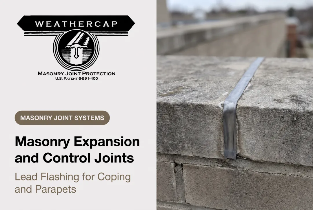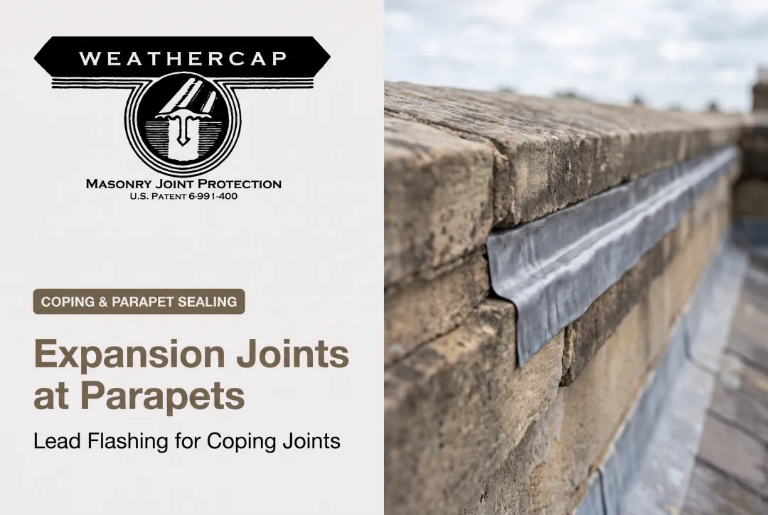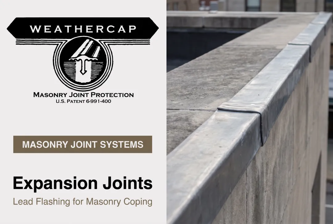

Horizontal joints take more abuse than vertical ones. Gravity pulls water into them instead of away. Moisture pools instead of shedding. And they sit at exactly the spots where buildings move the most: shelf angles, copings, parapets. Get these joints wrong, and you're looking at corroded steel, freeze-thaw spalling, and repair bills that dwarf the cost of doing it right the first time.
This article covers what horizontal expansion joints actually are, where codes and industry standards require them, how wide they need to be, and what separates a joint that lasts decades from one that fails in five years.
Key Takeaways
- Horizontal joints at shelf angles, copings, and parapets absorb movement that would crack masonry or blow out sealant
- Size joint width from wall height, material, and calculated differential movement—not a fixed default
- Sealant fails faster in horizontal joints than vertical ones; systems that shield it extend service life
What Is a Horizontal Expansion Joint?
A horizontal expansion joint is a continuous gap running along the horizontal plane of a masonry wall, typically located immediately below a shelf angle, at a parapet coping, or where two masonry planes meet at a right angle. Its job: let brick expand and structural framing deflect independently, without transferring stress into the wall.
The Brick Industry Association (BIA) describes brick as the only common building material with irreversible moisture expansion. That's why brick veneer needs these joints at every level where the wythe changes support.
Which Way Does an Expansion Joint Go?
Horizontal joints run parallel to the ground, typically at each floor line beneath shelf angles and at coping transitions. Vertical joints run up the wall face at set spacing intervals.
Orientation follows the stress each joint must absorb. Horizontal joints handle gravity-driven differential movement between the brick and the structural frame. Vertical joints handle lateral thermal expansion along the wall face.
Expansion Joint vs. Control Joint
These terms aren't interchangeable, and using the wrong one on a spec sheet causes real confusion:
- Expansion joints — used in clay brick, which has net overall expansion over time
- Control joints — used in concrete masonry unit (CMU) walls, which have net overall shrinkage
Both BIA and the Concrete Masonry & Hardscapes Association (CMHA) draw this line clearly. Ordinary CMU walls generally don't need horizontal control joints, since they aren't restrained from moving vertically. Brick veneer does—and those horizontal joints have to be detailed at every change in support.
Where Horizontal Expansion Joints Are Required
Below Shelf Angles
BIA Technical Note 18A is direct here: any brick wythe supported on a shelf angle needs a horizontal expansion joint beneath that angle. In multi-story construction, that means a joint at every floor line where the veneer transfers its load to a new angle. Skip this, and the brick below has nowhere to go when the frame above deflects.
At Copings and Parapets
Parapets move more than the rest of the wall because they're exposed on three sides with no dead load above to restrain them. BIA recommends:
- Extending vertical joints through the parapet, with intermediate joints spaced no more than 15 feet apart at the top
- Continuing those joints down to a horizontal joint, usually at the roof-level shelf angle
- Detailing copings to allow the wythes below to move independently of the cap

Weathercap's Type A flat cap is built specifically for this condition: it runs from the outer face, across the coping top, and down the parapet side.
Right-Angle Transitions
Wherever a cornice, belt course, water table, or lintel meets a parapet or side wall at roughly 90 degrees, the direction of movement changes abruptly. Weathercap's Type B 90° cove cap is designed for these coved, horizontal-to-vertical transitions.
Special Considerations
- Historic buildings: Investigate existing joint conditions before any restoration work begins
- Dark, south-facing walls: BIA notes these surfaces can reach 140°F when ambient air stays below 100°F, so plan for larger design temperature ranges and more movement
How Wide Should Horizontal Expansion Joints Be?
There's no universal number here, despite what a lot of stock details imply. BIA describes a typical ¼-inch unobstructed gap or highly compressible material beneath a shelf angle, but "typical" isn't "minimum." Joint width is a calculation, not a rule of thumb.
Width should account for:
- Brick's moisture and thermal expansion: calculated using BIA's veneer coefficients
- Frame movement: deflection, shrinkage, and creep in the structural support
- Shelf angle rotation: especially where one angle supports more than one story of veneer
- Wall height and orientation: taller runs and south-facing dark walls need more room
Before any restoration project, validate the existing joint width with a scratch gauge or a qualified consultant. Undersized joints concentrate stress instead of absorbing it, which accelerates failure rather than preventing it.
Whatever protective system fills that gap needs to handle the full range of anticipated movement without tearing, shearing, or losing adhesion. Weathercap's Type A and Type B products come in I.D. sizes that map to those calculated joint widths:
| Type A (Flat Cap) | I.D. Size | Type B (Cove Cap) | I.D. Size |
|---|---|---|---|
| A-2 | Under 3/8 in. | B-2 | Under 5/16 in. |
| A-3 | Under 7/16 in. | B-3 | Under 1/2 in. |
| A-4 | Under 3/4 in. | B-4 | Under 5/8 in. |
| A-6 | Under 1 1/4 in. | B-6 | Under 3/4 in. |
| A-8 | Under 1 1/2 in. | B-8 | Under 1 1/4 in. |

Final selection should factor in measured joint movement plus roughly a ¼-inch allowance for margin.
Common Failure Points and Why Sealant Alone Isn't Enough
Horizontal joints put sealant through more abuse than vertical ones. UV exposure, standing moisture, and constant flexing from building movement cause caulk to crack, shrink, or pull away from the substrate faster than it would in a vertical run.
One outdoor accelerated-weathering study, reported in Construction Specifier, tested 184 sealant specimens under cyclic movement. It found 29% failed overall, with unprimed specimens twice as likely to fail as primed ones. That's a controlled test, not a guarantee of field performance, but it makes the point: sealant by itself is a maintenance item, not a permanent fix.
When a horizontal sealant joint fails, water gets in behind the masonry. From there:
- Embedded steel corrodes
- Freeze-thaw cycling spalls brick and mortar
- Damage spreads before it's visible from the outside
A protective joint system closes that gap. Weathercap's patented soft lead strip (U.S. Patent 6991400) sits interposed within the sealed joint rather than replacing the sealant. The strip's underside grooves and anchor shaft embed into the sealant bed, physically occupying part of the joint opening. That reduces the effective joint size the sealant has to span by roughly half, cutting the stress the sealant absorbs during movement cycles.
The system is referenced in GSA Historic Preservation Technical Procedures (Document 07656-01) for use on parapets, copings, balustrades, cornices, and belt-course ledges. That includes corner and fillet joints where a horizontal surface meets a vertical one. It has been used across landmark restoration work at sites including the Washington Monument, the U.S. Supreme Court Building, and the Smithsonian Institution.
Best Practices for Long-Term Horizontal Joint Performance
Long-term horizontal joint performance depends on the process leading up to installation, not the material alone.
1. Investigate before you specify. Document existing joint spacing, throat opening width, and any visible cracking. Get validated movement data rather than assuming the original detail was correct.
2. Match the system to the exposure. For high-humidity or coastal climates, prioritize:
- Corrosion resistance
- Mold and mildew resistance on the sealant beneath
- Low thermal conductivity to limit thermal stress cycling
Soft lead conducts neither heat nor cold well, which helps reduce that cycling in exposed joints.
3. Plan for the finish, not just the function. On preservation-sensitive projects, the joint protection needs to disappear visually. Soft lead oxidizes fairly quickly from a silver-gray metallic finish to a dead neutral gray that reads as weathered stone. It can also be painted where a different finish is needed.
4. Coordinate at the design stage, not after cracking shows up. Retrofitting a failed joint is always more expensive than detailing it correctly from the start. Weathercap provides CAD drawings and sample specifications broken into General, Products, and Execution sections. Architects can build joint depth, backer rod placement, and sealant tooling into the drawings before construction starts.

Frequently Asked Questions
What is the purpose of an expansion joint?
Expansion joints absorb thermally and structurally induced movement in building materials. Without them, that movement transfers directly into the masonry, causing cracking and eventual water intrusion.
What is horizontal expansion?
Horizontal expansion refers to the gravity-driven and lateral movement masonry experiences along a horizontal plane. It's why joints are required below shelf angles and at coping transitions.
Which way does an expansion joint go?
Horizontal joints run parallel to the ground at floor lines and copings. Vertical joints run up the wall face at defined spacing intervals along the facade.
How wide can expansion joints be?
Width varies by material, wall height, and calculated movement. The Brick Industry Association (BIA) cites ¼ inch as a typical starting detail, but every project needs engineering validation rather than a copied number.
What's the difference between expansion joints and control joints?
Expansion joints handle irreversible expansion in materials like clay brick. Control joints handle shrinkage in materials like CMU. They aren't interchangeable on a spec sheet.