
When that "something" is missing or poorly detailed, the results show up fast. Cracked mortar. Water infiltration. Spalled brick faces. On historic masonry especially, an undersized or improperly placed joint can undo decades of careful preservation work.
This guide breaks down what causes masonry movement, how to detail an expansion joint correctly, and how specialized systems like WEATHERCAP® add a layer of long-term protection to these joints.
Key Takeaways
- Building movement is constant and unavoidable; joints are engineered to absorb that stress
- Joint width, depth, backer rod, and sealant all depend on anticipated movement calculations
- Movement joints are required at material changes, plane changes, and set spacing intervals
- WEATHERCAP® reduces effective joint opening by half when installed between sealant layers
- Poor or missing joint detailing remains a leading cause of masonry leaks and cracking—and is preventable with correct design
What Causes Building Movement in Masonry Construction?
Masonry doesn't sit still. Several forces act on it simultaneously, and each one demands a different design response.
Thermal expansion and contraction happens because brick, mortar, and stone react differently to temperature swings. According to the Brick Industry Association, brick has a thermal expansion coefficient of roughly 4 x 10⁻⁶ in./in./°F (small per degree, but significant) across a 100-foot facade during a seasonal swing (per BIA Technical Note 18).
Moisture-driven movement is often underestimated. Brick grows over its service life from irreversible moisture expansion. BIA cites a design coefficient of 3 x 10⁻⁴ in./in. for brickwork and up to 5 x 10⁻⁴ in./in. for veneer. Concrete masonry units move the other way, shrinking 0.24 to 0.54 inches per 100 feet as they lose moisture and carbonate.
Building settlement shows up as diagonal or stepped cracking, typically concentrated in mortar joints directly above the foundation. This is especially common in older structures where soil conditions have shifted over decades.
Seismic and wind-load movement adds lateral stress, particularly on taller or more exposed buildings where the facade flexes independently of the structural frame.
For anyone specifying joints, unaccounted-for movement is why most sealant joints eventually fail. A 2005 NIST study found that 55% of sealant joints fail within 10 years, and 95% fail within 20 (NIST, 2005). That failure rate is the default outcome unless movement is designed for from the start.

Anatomy of an Expansion Joint Detail: What Movement-Ready Joints Require
A properly detailed expansion joint has five components working together:
- Joint width — sized to the anticipated movement
- Joint depth — typically half the joint width
- Backer rod — controls sealant depth and shape
- Bond breaker — prevents unwanted adhesion
- Sealant — the flexible barrier itself
Calculating Joint Width
ASTM C1472 sets the equations for sealant joint size from anticipated movement, construction tolerances, and material behavior. In practice, BIA sizes a typical brick expansion joint like a mortar joint—usually 3/8 to 1/2 inch—with sealant depth at roughly half the width and a 1/4-inch minimum. Size backer rod about 25% larger than the joint width so it seats firmly without gaps. Those width and depth choices then change with joint orientation.
Horizontal vs. Vertical Joints
- Horizontal joints (copings, shelf angles): leave at least 1/4 inch of compressible space below shelf angles so the structure above can bear down without crushing the brick
- Vertical joints (corners, wall-to-wall transitions): place within 2 feet of a corner, or about every 10 feet along a run Stress patterns differ by orientation, so detailing—and often backer rod compression—should match the joint type.
The Two-Sided Adhesion Principle
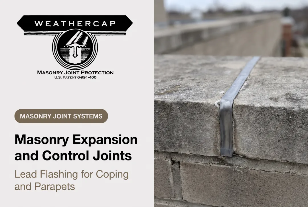
Sealant only flexes as designed when it bonds on two sides, not three. A bond breaker—the backer rod itself or separate tape—limits adhesion to the two joint faces. Without it, the sealant tears internally instead of stretching. Right-angle wall junctions and copings atop parapets concentrate movement where multiple planes meet. Standard detailing often falls short there, so drawings should lock in joint dimensions, materials, and placement instead of leaving those calls to the field. On these high-stress geometries, a protective lead cap over the sealed joint (such as Weathercap) can buffer movement at the sealant face and reduce premature joint failure.

How WEATHERCAP® Reinforces Movement Joint Details in Masonry
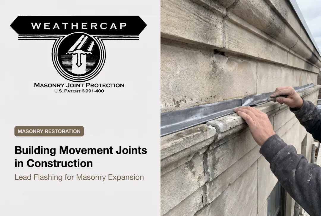
WEATHERCAP® is a patented (U.S. Patent 6991400) soft lead strip system designed to sit inside a sealed masonry joint and absorb ongoing movement as an adjunct to the sealant.
How it works: The lead strip is interposed between layers of sealant. Because it deforms easily under low stress, it reduces the effective joint opening that the sealant itself has to bridge—by half, according to product specifications. Less movement reaching the sealant means longer sealant life and less frequent resealing.
Material properties that make this possible:
- Low creep strength and low elastic modulus let the lead reshape as the joint moves, including under temperature-driven creep
- Tear and shear resistance holds up under repeated stress cycles instead of failing after a few movement events
- Corrosion, mold, and mildew resistance suit humid, high-exposure masonry environments
- Neutral grey oxidation blends with most masonry naturally, or can be painted to match
WEATHERCAP® comes in two configurations:
| Product Type | Application | Joint Sizes |
|---|---|---|
| Type A (Flat Cap) | Coping tops, balustrades, cornice cross joints | A-2 (under 3/8") through A-8 (under 1.5") |
| Type B (90° Cove Cap) | Right-angle junctions where cornices/belt courses meet a wall | B-2 (under 5/16") through B-8 (under 1.25") |
Once you pick a type, sizing follows a straightforward formula: joint opening, plus the maximum anticipated movement percentage from sealant manufacturer scribe testing, plus 1/4 inch. That total becomes the cap's installed outer dimension.
That same movement-critical detail is why the system appears in GSA Historic Preservation Technical Procedures (Document 07656-01) for vulnerable joints at parapets, copings, and cornices. WEATHERCAP® has been used on landmark restoration projects including the Washington Monument, the U.S. Supreme Court, and the Smithsonian Institution, where joints face decades of weather exposure and repeated building movement.

Movement Joint Types, Spacing & Governing Standards
Not every gap in a masonry wall is the same kind of joint. Three categories matter most:
- Control joints — planned weak points that let masonry crack in a controlled, hidden location instead of randomly
- Isolation joints — gaps that separate masonry from structural elements that move differently (columns, slabs)
- True expansion/movement joints — full-depth gaps designed specifically to absorb thermal and moisture-driven dimensional change
Spacing guidance varies by exposure and geometry, but BIA Technical Note 18A offers general benchmarks:
- Vertical brick joints with no openings: maximum 25 feet on center
- Vertical joints with multiple openings: maximum 20 feet on center
- Parapets: joints no more than 15 feet apart at the top
- Corners: first joint within 2 feet, or within roughly 10 feet along one adjacent side
These are starting points, not universal rules. Material type, sun exposure, and building geometry all shift the actual spacing a project needs.
Once joint locations are set, sealant performance keeps those gaps weathertight under movement. Sealant selection should meet ASTM C920, which governs cured elastomeric joint sealants for cold-applied caulking and glazing work. C920 classifies sealants by type (single or multicomponent), grade (pourable or non-sag), and movement class, so specifiers can match flexibility to the joint's expected motion.

Installation & Long-Term Maintenance of Expansion Joint Details
Detailing on paper only matters if installation matches it.
Surface preparation is non-negotiable. Joints must be raked clean before anything new goes in:
- Old mortar, dust, and degraded sealant removed
- Stone and lead strip clean and dry
- For WEATHERCAP®, joint depth cut to anchor shaft length plus 1/4 inch
Ongoing inspection catches problems early. Hoffmann Architects recommends a full building-envelope inspection at least twice annually, with checks for:
- Sealant failure and cracking
- Mortar deterioration
- Signs of displacement from building movement
ASTM C1521 provides destructive and nondestructive methods for evaluating adhesion on installed sealant joints—useful when a facade shows early warning signs.
For restoration and landmark work, manufacturer documentation is required, not optional. WEATHERCAP® provides CAD drawings and sample specifications through its technical documentation, organized into general, product-specific, and execution sections.
Those materials cover backer-rod placement, sealant allowances, and installation sequencing so the joint is detailed correctly the first time instead of after a leak appears.
Frequently Asked Questions
What are the construction details of an expansion joint?
A typical detail includes calculated joint width and depth, a backer rod or bond breaker to control sealant shape, and a flexible sealant rated for the anticipated movement. Dimensions are derived from expected thermal and moisture movement, rather than fixed defaults.
What is the main purpose of an expansion joint?
It absorbs building movement from temperature swings, settlement, or seismic activity, preventing that stress from transferring into rigid masonry or overstressing the sealant itself.
At what distance is an expansion joint required?
Spacing depends on material, exposure, and building geometry. BIA suggests roughly 20-25 feet for vertical brick joints, but project-specific engineering or manufacturer guidance should always confirm the final spacing.
How wide should an expansion joint be in a brick wall?
Width is calculated from anticipated thermal and moisture movement over the joint spacing distance, typically 3/8 to 1/2 inch for standard brick applications. Undersized joints are a leading cause of sealant failure.
How far apart should drywall expansion joints be?
Drywall control joints follow separate interior guidelines. Common industry references cite maximum spacing around 30 feet without perimeter relief, and up to 50 feet with it, to prevent cracking from framing movement.