
Most cracking isn't a masonry failure. It's a design failure. Building codes place the responsibility for locating movement joints squarely on the designer, not the mason pouring or laying units on site.
This guide covers joint types, spacing rules, correct widths, placement strategy, and how to protect joints once they're installed.
Key Takeaways
- Expansion joints accommodate clay brick's irreversible moisture growth; control joints manage CMU shrinkage cracking
- BIA and TMS 402 set maximum spacing intervals based on wall material, height, and openings
- A ½-inch joint width with correctly sized backer rod is the standard target for long-term sealant performance
- TMS 402/602 assigns joint location and detailing responsibility to the designer, not the installing contractor
What Are Masonry Expansion and Control Joints?
Expansion Joints (Clay Brick)
Fired clay brick starts small. It cools after leaving the kiln, then spends years absorbing ambient moisture and expanding permanently. Most of that growth happens in the first few weeks off the kiln, but a slower increase continues indefinitely.
The Brick Industry Association pegs this at a design coefficient of 3 x 10⁻⁴ in./in. for brickwork and 5 x 10⁻⁴ in./in. for brick veneer, per its Technical Note 18.
An expansion joint gives that growth a place to go instead of pushing against adjacent panels.
Detailing rules that matter:
- Sealant should meet ASTM C920, Grade NS, Use M
- BIA recommends Class 50 sealant as the minimum, with Class 25 as an alternate, not the default
- The joint cavity must stay clear of mortar droppings, steel ties, and debris that could restrict compression
Control Joints (CMU)
Concrete masonry units behave the opposite way. CMU shrinks as it cures and continues to lose moisture over its service life. A control joint creates a deliberate vertical weak plane. Shrinkage cracking then follows a straight, planned line instead of a random diagonal through the block face.
Horizontal joint reinforcement (ladder or truss wire) works alongside control joints; it doesn't replace them. Reinforcement resists tensile stress across the wall. The control joint still has to define where the shrinkage plane occurs.
A common design mistake: treating "control joint" and "expansion joint" as interchangeable terms. They solve opposite problems. Brick grows; CMU shrinks. Mixing up the detail means specifying the wrong joint for the wrong material.
How Far Apart Should Expansion and Control Joints Be?
Spacing guidelines set a maximum, not a default layout. Here's what the Brick Industry Association (BIA) and the Concrete Masonry & Hardscapes Association (CMHA) recommend:
| Assembly | Maximum Spacing |
|---|---|
| Brick veneer, no openings | 25 ft |
| Brick veneer, multiple openings | 20 ft |
| Brick parapets | 15 ft |
| CMU, 8-in nominal units | 25 ft 4 in (or 1.5:1 length-to-height) |
| CMU, 4-in nominal units | 20 ft (or 1.5:1) |
| Concrete masonry veneer | 20 ft (or 1.5:1) |

Source: BIA Technical Note 18A and CMHA CMU-TEC-009-25.
The 1.5:1 rule for CMU: panel length shouldn't exceed 1.5 times the wall height. CMHA's own worked example compares 1.5 × 20 ft (30 ft) against the fixed 25 ft 4 in maximum. The lower number governs.
A few factors tighten these intervals further:
- Openings: windows and doors interrupt wall continuity and concentrate stress at jambs
- Reinforcement: the table assumes a specific horizontal reinforcement condition; changing it shifts the allowable interval
- Exposure: dark, south-facing, or high-temperature-swing walls move more and need closer spacing than the table maximums
How Wide Should Expansion Joints Be?
The Brick Industry Association (BIA) sizes a typical expansion joint to resemble a mortar joint: 3/8 inch to 1/2 inch. Half an inch is the common design target on most projects. Undersizing the joint is a frequent, avoidable cause of brick spalling: the brick has nowhere to expand into, so it crushes against its neighbor at the joint face.
Backer rod and sealant sizing:
- Backer rod diameter should run roughly 25% larger than the joint width, so it seats under compression instead of falling through
- Sealant depth should be about half the joint width, with a 1/4 inch minimum
- Sika's backer rod guidance recommends sizing it 1/8 inch larger than the joint opening. Check the manufacturer spec sheet against the BIA rule for your project

Expansion joints must stay completely free of mortar droppings. Control joints can tolerate a bit more debris since they're designed to crack, not compress.
Where to Place Movement Joints: Key Locations
Spacing tables give you a ceiling. Actual placement should follow the stress points in the wall, not a uniform grid.
Corner Placement
BIA's preferred rule: locate a joint within roughly 2 feet of the corner on either wall. If that isn't achievable, place a joint within about 10 feet of at least one side of the corner. The combined distance from the corner to the first joint on each side still shouldn't exceed standard straight-wall spacing.

Openings and Transitions
- Brick: align expansion joints with window and door jambs where possible, rather than running a joint mid-panel
- CMU: use reinforced or isolated detailing around openings instead of relying on the standard spacing interval alone
- Material or height changes: any transition (thickness, material, or roofline step) is a stress point that needs a joint, regardless of spacing tables
The Documentation Problem
The most common design failure is poor communication, not bad math. A spec note reading "provide control joints at 25 ft maximum" tells the contractor nothing about where. TMS 402/602 public comment records flag this explicitly: generic notes create real problems at flanged shear walls, lintels designed using arching action, and wall intersections. Joint locations belong on the drawings and elevations, not buried in a spec paragraph.
Protecting and Sealing Movement Joints for Long-Term Performance
Sealant alone has a lifespan. Every building movement cycle — thermal expansion, seasonal humidity, settlement — puts the sealant bead under repeated stress. Eventually it tears, shears, or loses adhesion, and water starts finding its way behind the wall.
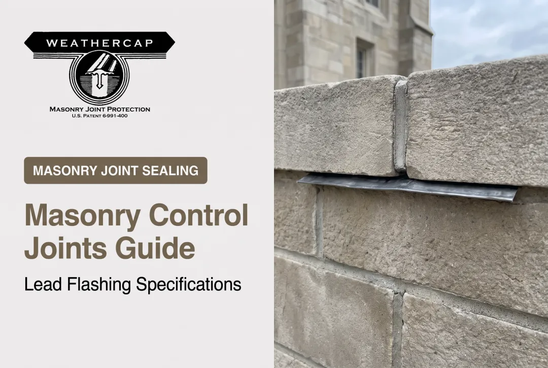
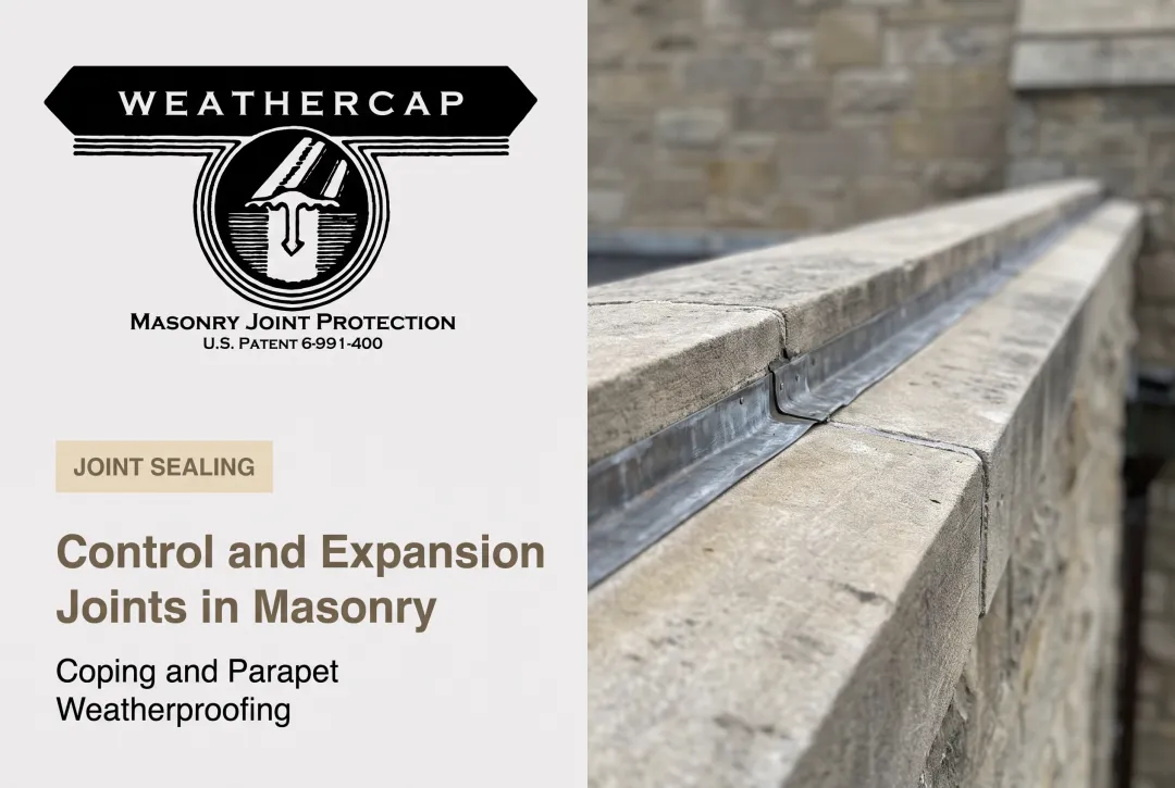
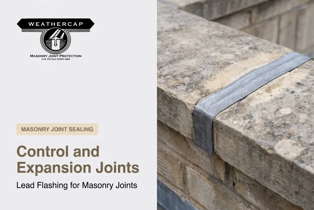
This is the gap Weathercap's patented soft lead strip system was built to close. Rather than replacing sealant, it's interposed within the sealed joint as an adjunct layer. The lead strip absorbs a share of the stress cycle, reducing the effective joint opening the sealant must accommodate by roughly half.
How it works on-site:
- Rake and clean the joint to accommodate the anchor shaft plus ¼ inch.
- Set backer rod ¼ inch below the anticipated anchor-shaft tip.
- Fill the joint with sealant to about ⅛ inch above the masonry surface.
- Press the pre-contoured strip firmly into the sealant until no voids remain.

Once the joint is sealed, product choice depends on geometry. Weathercap ships two configurations: Type A (flat cap, for horizontal and vertical joints) and Type B (a 90-degree cove cap for right-angle conditions like coping-to-parapet transitions). Sizes cover joint openings from 5/16 inch up to 1.5 inches I.D., shipped in 6-foot lengths and mitered, coped, or butted at transitions.
The system has been used on 28+ nationally significant landmarks, including the Washington Monument, U.S. Supreme Court, and Smithsonian Institution. It is specified in the GSA Historic Preservation Technical Procedures (Document 07656-01).
Beyond stress absorption, the lead surface delivers lasting field performance:
- Oxidizes to a neutral gray that blends with existing masonry
- Resists corrosion and mold in exposed conditions
- Accepts paint to match surrounding finishes
Common Mistakes That Cause Joint Failures
Most joint failures trace back to one of a handful of recurring errors:
- Wrong joint type for the material: specifying a control joint where an expansion joint was needed, or vice versa
- Excessive or inconsistent spacing: exceeding BIA/CMHA maximums, or spacing joints unevenly across a facade
- Skipping joints to save cost: omitting joints at corners or openings because the drawings didn't call them out
- Poor sealant installation: undersized backer rod, wrong sealant class, or debris left in the joint cavity
Per TMS 402/602, the designer bears responsibility for locating and detailing movement joints. A mason following a spec note that says "provide joints as required" has no way to know where "required" means. The failure is a documentation gap, and it shows up as cracking years later.
Frequently Asked Questions
How far apart should masonry expansion joints be in a brick wall?
BIA recommends a maximum of 25 feet for brick veneer without openings, tightening to 20 feet where multiple windows or doors interrupt the wall. Parapets need closer spacing, around 15 feet, due to added exposure.
How wide should masonry expansion joints be in a brick wall?
The standard target is ½ inch, though BIA allows a range from 3/8 to 1/2 inch. Backer rod should run about 25% larger than the joint width to seat properly under compression.
What's the difference between an expansion joint and a control joint?
Expansion joints accommodate clay brick's irreversible moisture growth over time. Control joints manage concrete masonry's shrinkage by creating a predictable weak plane. They solve opposite movement problems and aren't interchangeable.
Who is responsible for locating movement joints on a project?
TMS 402/602 assigns this responsibility to the designer or architect of record, not the mason installing the wall. Joint locations should appear on drawings and elevations, not just in a generic spec note.
Can old, failing sealant joints be repaired without full replacement?
Weathercap's lead strip system can be installed over prepared, cleaned-out joints to extend sealant life going forward. Full removal of failed old caulk and proper joint prep is still required before installation.